Geely Emgrand X7. Manual part - 401


  Главная      Geely     Geely Emgrand X7 - Manual


поиск по сайту            


содержание   ..  399  400  401  402  ..


Geely Emgrand X7. Manual part - 401


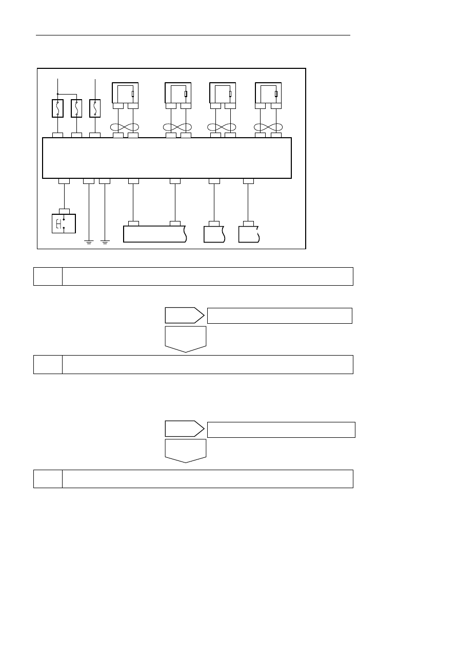
6.6.6.8 Keeping ABS Warning Light Normally On 

Circuit diagram: 

NL06-1011b

3 CA13

78 EN01

17 CA13

7 IP12

16 CA13

13 IP01

32 CA13

30 CA13

2 IP56

4 CA13

13 CA13 38 CA13

31 IP01

R

18

2

CA13

CA16

6

1

CA13

CA16

34

2

CA13

CA07

22

1

CA13

CA07

10

A

IF34

1 CA13

40A

EF04

25 CA13

25A

EF03

IG

+BRAKE LIGHT SW

GND

GND

EBD WARING LMP

ABS WARING LMP

SENSOR OUTPUT

RR WHEEL

DIAGNOSTIC K

WP RR WS RR

WP FR

WS FR

WP FL

WS FL

WP RL WS RL

制动灯
开关

左后轮速
传感器

右后轮速
传感器

左前轮速
传感器

33

2

CA13

SO28

20

1

CA13

SO28

19

2

CA13

SO25

31

1

CA13

SO25

右前轮速
传感器

ABS控制模块

IG2

ALT

ECM

诊断接口

组合仪表


Diagnostic Steps: 

The ABS control module is accessed via a diagnostic unit. 

A. Check whether DTC is faulty 


Inspect the battery. 

A. Measure the voltage of the accumulator with the multimeter. 

Standard Voltage: 11-14 V 

B. Confrim whether the voltage is at a specified Value. 


Check    ABS control module harness connector 

A.  Inspect whether the harness connector is connected correctly. 

Repair the circuit according to DTC output 

Charge the battery or inspect the charging 

No 

Yes 

Yes

No 

ABS control module

Right 

rearspeed 

sensor 

Left rear 

speed 

sensor

Right 

front 

speed 

sensor

Left front 

speed 

sensor

Brake 

lamp 

switch 

Combination instrument 

Diagnostic
s interface

1603


Check ABS control module harness connector ( terminal voltage) 


(a)  Turn off the ignition switch. 

B.   Disconnect the harness connector of the control 

module. 

C.    Turn on the ignition. 

D.  Measure the voltages between Terminals 1, 25 

and 32 of the harness connector CA13 and the 
body ground wire. 


NL06-1012b

25

1

26

27

28

29

30

31

32

33

34

35

36

37

38

13

24

12

14

15

16

17

18

19

20

21

22

23

2

3

4

5

6

7

8

9

10

11

CA13 ABS控制模块线束连接器

25

1

32


Standard Voltage: 11-14 V 

E.  Confirm if the voltage conforms to standard value. 


Check    ABS control module harness connector (grounding terminal Continuity) 


A. A universal meter is used for measuring the 

resistance among the terminals 13 and 38 of the 
connector CA13 and the body grounding. 

Standard Resistance: Less than 1 Ω 

B.  Confirm whether the resistance is the standard 

value. 

NL06-1013b

25

1

26

27

28

29

30

31

32

33

34

35

36

37

38

13

24

12

14

15

16

17

18

19

20

21

22

23

2

3

4

5

6

7

8

9

10

11

CA13 ABS控制模块线束连接器

38

13


Check fuse, repair or replace harness 

Connect the harness connector properly. 

Yes

No 

Yes

No 

CA13ABS control module harness 

connector


CA13ABS control module harness 

connector


1604


Replace hydraulic electric control unit assembly 

(a) Replace hydraulic electric control unit, refer to 6.6.7.1 hydraulic electric control unit replacement. 

(b) Connect to positive of battery. 

(c) Turn on ignition switch, confirm if ABS warning lamp is ON after go out. 


Inspect the combination instrument. 

A. Connect the diagnostic tester. 

B. Selected “Active test” on the function test 

Active test:ABS 

Tester display 

Testing part 

ABS warning lamp 

ABS warning lamp light on or is not light up (ON / OFF) 

. Check whether the ABS warning lamp works normally. 


Replace control unit of combination instrument   

(a) Disconnect the battery negative electrode cable. Refer to 2.11.8.1 Battery Disconnection. 

(b) For replacement of combination instrument control unit, refer to the replacement of combination instrument 
assembly. 

(c)  Confirm the repair is completed. 


The system is normal. 

Repair or replace the wire harness or the wire 

The system is normal. 

Yes 

No 

No 

Yes 

No 

Yes 

The system is normal. 

Next 

1605


6.6.6.9 ABS warning Light is not on under all circumstances 

Circuit diagram: 

NL06-1011b

3 CA13

78 EN01

17 CA13

7 IP12

16 CA13

13 IP01

32 CA13

30 CA13

2 IP56

4 CA13

13 CA13 38 CA13

31 IP01

R

18

2

CA13

CA16

6

1

CA13

CA16

34

2

CA13

CA07

22

1

CA13

CA07

10

A

IF34

1 CA13

40A

EF04

25 CA13

25A

EF03

IG

+BRAKE LIGHT SW

GND

GND

EBD WARING LMP

ABS WARING LMP

SENSOR OUTPUT

RR WHEEL

DIAGNOSTIC K

WP RR WS RR

WP FR

WS FR

WP FL

WS FL

WP RL WS RL

制动灯
开关

左后轮速
传感器

右后轮速
传感器

左前轮速
传感器

33

2

CA13

SO28

20

1

CA13

SO28

19

2

CA13

SO25

31

1

CA13

SO25

右前轮速
传感器

ABS控制模块

IG2

ALT

ECM

诊断接口

组合仪表


Diagnostic Steps: 

1 Inspect 

the 

battery. 

A. Measure battery voltage. 

Standard voltage: 11-14 V 

B. Confrim whether the voltage is at a specified value. 


Inspect the combination instrument connector. 

A. Turn the ignition switch to OFF position. 

B. Disconnect the negative (-) cable from the accumulator. 

C. Check whether the connector is correctly connected to the combination instrument assembly. 


Inspect and replace the battery or 
charge system. 

Correctly connect the connector. 

Yes 

No 

Yes

No 

ABS control module

Right 

rearspeed 

sensor 

Left rear 

speed 

sensor

Right 

front 

speed 

sensor

Left front 

speed 

sensor

Brake 

lamp 

switch 

Combination instrument 

Diagnostic
s interface

1606


содержание   ..  399  400  401  402  ..