содержание .. 334 335 336 337 338 339 340 ..
Geely Emgrand X7. Manual part - 339
A. rotated ignition switch to OFF position.
B. Disconnect the harness connector J-4 of the
electromagnetic valve.
C. Measure the resistance between Terminal 4 of the
electromagnetic valve harness connector J-4 and
Terminal 3 of the automatic control module J-1.
D. Measure the resistance between Terminal No.1 of
the electromagnetic valve harness connector J-4
and Terminal 7 of the automatic control module
J-1.
E. Turn the ignition switch to the ON position.
F. Measure voltage of electromagnetic valve
harness connector J-4No.4 terminal and reliable
grounding
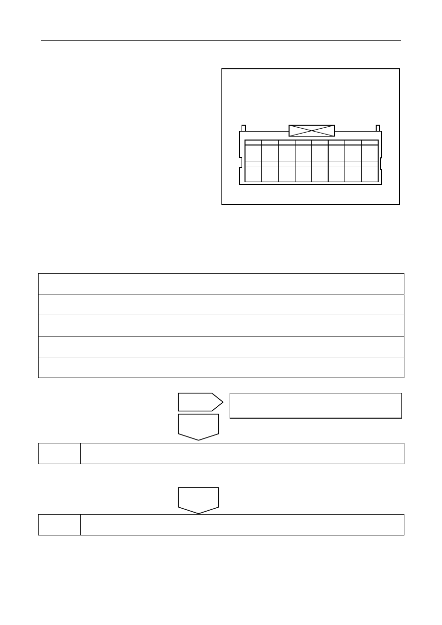
自动变速器控制模块线束连接器
J-1
1
9
2
10
3
11
4
12
5
13
6
14
7
15
8
16
SL03-0034c
G. Measure the resistance between Terminal No.1 of the electromagnetic valve harness connector J-4 and secure
ground wire.
Results
Test items
Standard value
J-4 (4) — J-1(3)
Less than 3 Ω
J-4 (1) — J-1(7)
Less than 3 Ω
J-4 (4) — Reliable grounding voltage value
0 V
J-4 (1) — Reliable grounding resistance value
Less than 3 Ω
Does it conform to the standard value?
4 ReplaceTCU
Refer to3.5.7.8 replace automatic transmission control module
5
Go to automatic transmission fresh process.
Refer to3.5.7.4 Automatic transmission refresh process
No
Yes
Circuit malfunction, repair circuit.
Next
Auto-transmissioncontrol module harness connectorJ-1
1355