Geely Emgrand X7. Manual part - 327


  Главная      Geely     Geely Emgrand X7 - Manual


поиск по сайту            


содержание   ..   324  325  326  327  328  ..


Geely Emgrand X7. Manual part - 327


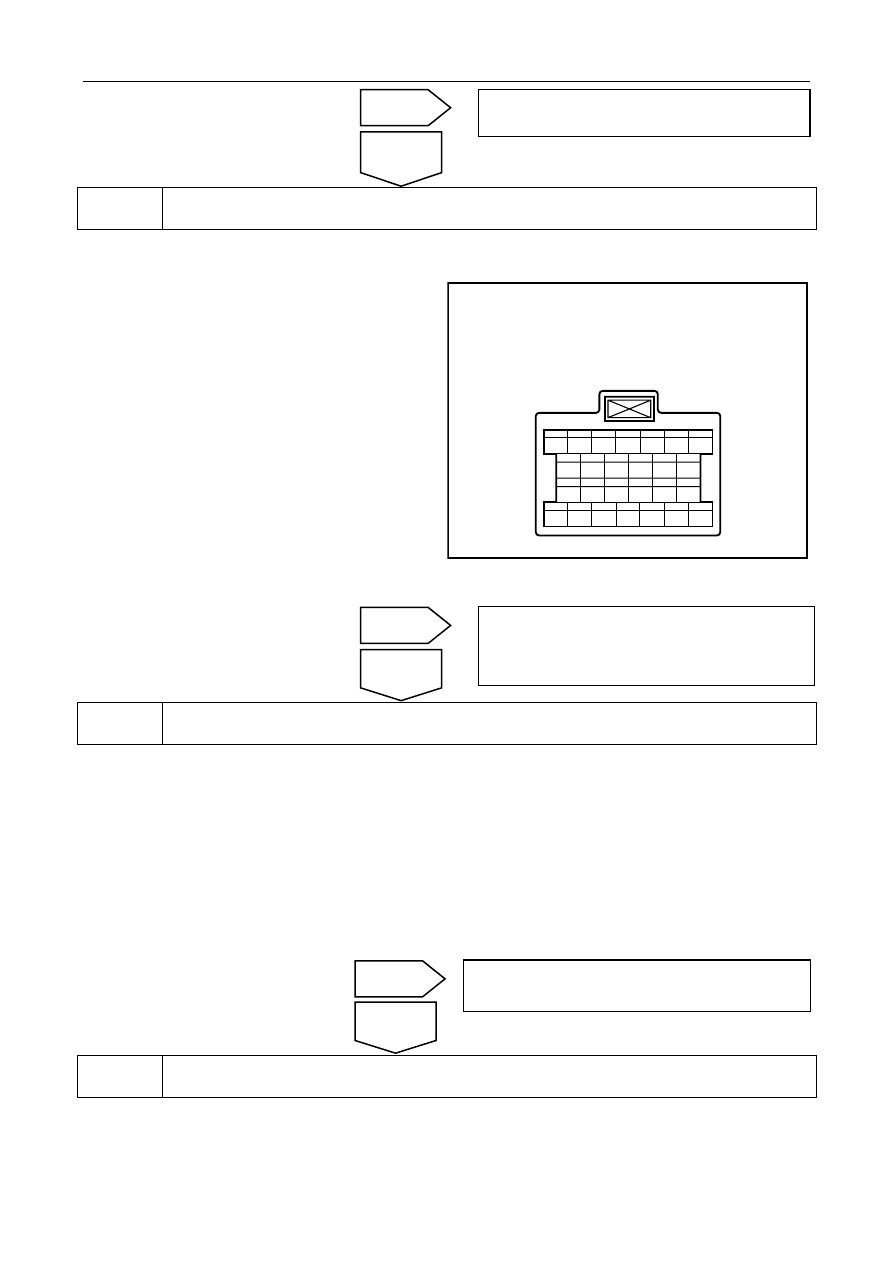
Detect the reference voltage of the input shaft speed sensor. 


A.    Turn the ignition switch to the OFF position. 

B.  Disconnect the harness connector J-4 of the 

electromagnetic valve. 

C.    Turn the ignition switch to the ON position. 

D.    Measure the voltage between terminals 8 and 9 of 

the electromagnetic valve harness connector J-4. 

Standard voltage values: is more than10V 


电磁阀线束连接器 J-4

1

8

20

14

9

15

10

16

11

17

12

18

13

19

2

21

3

22

4

23

5

24

6

25

7

26

SL03-0036c

Does it conform to the standard value? 


Detect the signal voltage of the input shaft speed sensor. 

A.    Turn the ignition switch to the OFF position. 

B.    Disconnect the harness connector J-4 of the electromagnetic valve. 

C.    Turn the ignition switch to the ON position. 

D.    Measure the voltage between Terminals 8 and 11 of the electromagnetic valve harness connector J-4. 

Standard voltage: 4.9-5.1 V 

Does it conform to the standard value? 


Detect the circuit of the input shaft speed sensor. 

No

Yes 

Refer to3.4.7.6 fault diagnosis code (DTC) 
chapter index

No

Yes

Refer to 3.4.7.8 Replacement of automatic 

transmission control module to replace TCU. 

No

Yes

Refer to 3.4.7.8 replacement of automatic 
transmission control module to replace TCU. 

Electromagnetic valveharness connectorJ-4

1307


A.  Rotated ignition switch to OFF position. 

B.  Disconnect the harness connector J-4 of the 

electromagnetic valve. 

C.    Measure the resistance between terminal No.8of 

the electromagnetic valve harness connector J-4 
and Terminal No.12 of the automatic control 
module J-3. 

D.    Measure the resistance between terminal 9 of the 

electromagnetic valve harness connector J-4 and 
Terminal No.2 of the automatic control module 
J-3. 

E.  Measure resistance of electromagnetic valve 

harness connector J-4 No ,11 terminal and 
Automatic transmission control 
moduleJ-3Terminal No.3   

自动变速器控制模块线束连接器

J-3

1

11

2

12

3

13

4

14

5

15

6

16

7

17

8

18

9

19

10

20

SL03-0036c

F.  Turn the ignition switch to ON position. 

G.    Measure the voltage between Terminal No.8of the electromagnetic valve harness connector J-4 and secure 

ground wire. 

H    Measure voltage of electromagnetic valve harness connector J-4 terminal No.9 and reliable grounding 

Measure voltage of electromagnetic valve harness connector J-4   No. 1 terminal No. 1 and reliable grounding 

Results 

Test Items 

Standard value 

J-4(8) — J-3(12) 

Less than 3 Ω 

J-4(9) — J-3(2) 

Less than 3 Ω 

J-4(11)— J-3(3) 

Less than 3 Ω 

J-4(8) — Reliable grounding voltage value 

O V 

J-4(9) — Reliable grounding voltage value 

0 V 

J-4(11) — Reliable grounding voltage value 

O V 

Does it conform to the standard value? 


Detect the output waveform of the input shaft speed sensor. 

No

Yes

Circuit malfunction, repair circuit. 

Auto-transmissioncontrol module harness connectorJ-3

1308


A.    Turn the ignition switch to the OFF position. 

B.    Connect an oscilloscope to    terminals No.3 and 

12 of the harness connector J-3 of the automatic 
transmission control module. 

C.    Turn the ignition switch to the ON position. 

D.    Start up the engine and increase the engine RPM 

to observe whether the waveform on the 
oscilloscope is as shown in the right figure. 

SL03-0038c

Is the waveform consistent with the right figure? 


6 Replace 

TCU 

Refer to3.5.7.8 replace automatic transmission control module 


Go to automatic transmission fresh process. 

Refer to3.5.7.4 Automatic transmission refresh process 


Use fault diagnosis tester to confirm if DTC is stored again. 

A.    Connect fault diagnosis tester to the data link connector. 

B.  Rotated ignition switches to ON position. 

C.    Clear DTC code. 

D.    Start and run the engine at idle speed to warm up the engine for at least 5min. 

E.    Read control system DTC code again to confirm that the system has no DTC code exported. 

No

Yes 

Replace auto-transmission assembly, refer to3.4.7.6 
replace auto-transmission assembly 

Next 

Next 

1309


9 Troubleshooting 

5. Maintenance 

guide: 

Replace Automatic transmission control module, refer to3.5.7.8 replace automatic transmission control module 

Replace Automatictransmission assembly; refer to3.5.7.6 Automatictransmission assembly replacement 

Yes 

No

Refer to 2.2.7.3 Intermittent Fault Inspection for 
intermittent fault. 

1310


содержание   ..   324  325  326  327  328  ..