содержание .. 321 322 323 324 325 326 327 ..
Geely Emgrand X7. Manual part - 326
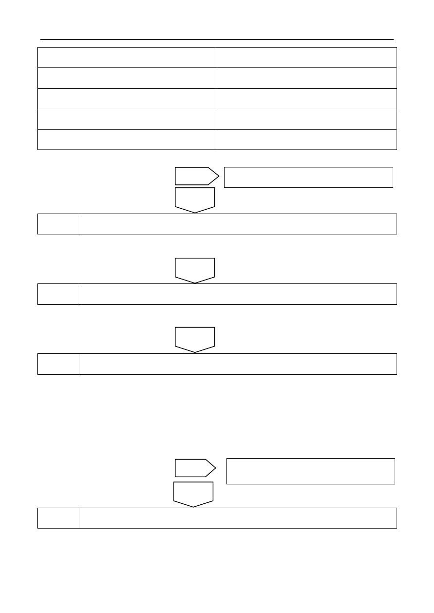
J-4(13) — J-3(14)
Less than 3 Ω
J-4(8) — Reliable grounding voltage value
O V
J-4(9) — Reliable grounding voltage value
0 V
J-4(12) — Reliable grounding voltage value
O V
J-4(13) — Reliable grounding voltage value
0 V
Does it conform to the standard value?
3 ReplaceTCU
Refer to3.5.7.8 replace automatic transmission control module
4
Go to automatic transmission fresh process.
Refer to3.5.7.4 Automatic transmission refresh process
5
Use fault diagnosis tester to confirm if DTC is stored again.
A. Connect fault diagnosis tester to the data link connector.
B. Rotated ignition switches to ON position.
C. Clear DTC code.
(d). Start and run the engine at idle speed to warm up the engine for at least 5min.
(e) Read control system DTC code again to confirm that the system has no DTC code exported.
6 Troubleshooting
5. Maintenance
guide:
Replace Automatic transmission control module, refer to3.5.7.8 replace automatic transmission control module
No
Yes
Circuit malfunction, repair circuit.
Next
Yes
No
Next
Refer to 2.2.7.3 Intermittent Fault Inspection for
intermittent fault.
1303