Geely Emgrand X7. Manual part - 203


  Главная      Geely     Geely Emgrand X7 - Manual


поиск по сайту            


содержание   ..   200  201  202  203  204  ..


Geely Emgrand X7. Manual part - 203


4. Diagnostic 

Steps: 

Note: Before carrying out this diagnosis step, observe the data list on fault diagnosis tester and 
analyze the accuracy of the data, as these will help with quick diagnosis. 

Step 1


Initial Inspection 

(a)Inspect the fuel injector harness connector for damage, poor connection, aging or signs of 
loosening 


Step 2


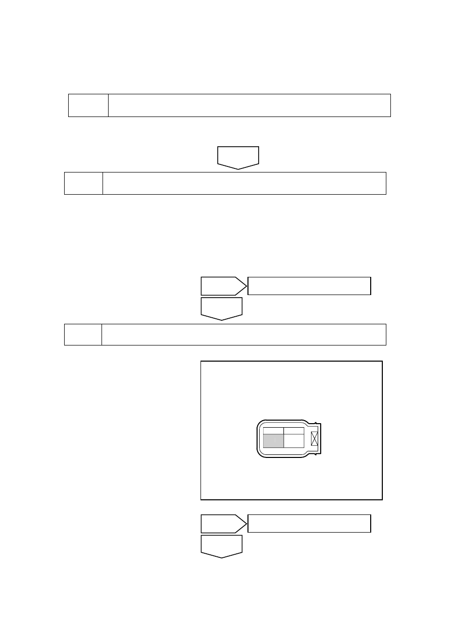
Measure the fuel injector resistance. 

(a)  Disconnect the fuel injector harness connector EN14. 

(b)  Measure resistance between the two fuel injector terminals. 

Standard Resistance 

11.5-12.6Ωwith 20℃(68 

(c)  Connect the fuel injector harness connector EN14. 


(a)  Rotated ignition switch to OFF 

position . 

(b) 

Disconnect 4-cylinder fuel 
injector harness connector EN14.

(c)  Rotated ignition switch to ON 

position . 

(d) 

Measure voltage between 
cylinder No.4 fuel injector wiring 
harness connector EN14 No.A 
terminal and a reliable ground. 

Standard Voltage: 11-14V 

(e) Connect to 4 cylinder fuel 

injector harness connector EN14.

NL02-2094b

A

B

EN14 4缸燃油喷射器线束连接器

A


Measure Fuel Injectors Working power supply 

No 

Go to step 5 

Yes 

No 

Refer to 2.2.8.2 “Replacement of Fuel 
Injectors” to replace the fuel injectors 

Yes 

Next 

EN14 4th cylinderfuel injector 

811


(a)  Rotated ignition switch to OFF 

position . 

(b) 

Disconnect 4-cylinder fuel 
injector harness connector EN14.

(c)  Connect a light-emitting diodes 

test lamp to the fuel injector 
wiring harness connector EN14 
terminal No.A and B. 

(d) Start 

the 

engine. 

(e)  Observe whether test lamp is 

flashing. 

NL02-2095b

A

B

EN14 4缸燃油喷射器线束连接器

A

B

Is test lamp flashing as normal? 


Step 5


Inspect and repair cylinder No.4 fuel injector power circuit. 


(a)  Rotated ignition switch to OFF 

position . 

(b) Disconnect the fuel injector 

harness connector EN14. 

(c)  Dismantle the engine main relay. 

(d) Measure  resistance  between 

cylinder No.4 fuel injector wiring 
harness connector EN14 terminal 
No.B and engine main relay 
terminal No.30. 

(e) Measure  resistance  between 

cylinder No.2 fuel injector wiring 
harness connector EN14 terminal 
No.B and a reliable ground. 

ER03

85

86

87

30

30

87

86

85

ER05

30

87

86

85

ER06

30

87

87a

86

85

ER11

ER08

ER0

9

85

86

87

30

ER10

2

1

5

3

2

1

5

3

2

1

5

3

ER04

ER02

2

1

5

3

2

1

5

3

ER01

ER07

2

1

5

3

1

2

3

4

11

12

13

14

15

16

5

6

7

8

9

10

EF0

8

EF0

7

EF2

7

EF2

6

EF2

2

EF2

9

EF0

3

EF0

6

EF0

9

EF2

5

EF1

7

EF1

6

EF1

5

EF3

5

EF2

1

EF

1

4

EF

0

1

EF

0

2

EF

0

4

EF

1

0

EF

1

1

EF

1

8

EF

2

4

NL02-0045c

Step 4


Inspect the fuel injector control circuit. 

Go to step 6 

Go to step 7 

No 

Yes 

EN14 4th cylinderfuel injector 

812


NL02-2094b

A

B

EN14 4缸燃油喷射器线束连接器

A

Standard Resistance 

Test Items 

Standard Value 

Resistance Between EN14 (b) and Main Relay Terminal No.30 

Less than 1 Ω 

Resistance Between EN14 (b) and A Reliable Ground 

10 kΩ or higher 

(f)  Install the engine main relay. 

(g)  Connect cylinder 4 fuel injector wire harness connector EN14. 

Exclude the fuel injector power supply circuit fault. 


Step 6


Inspect the Cylinder #4 fuel injector control circuit. 


(a)  Rotated ignition switch to OFF 

position . 

(b) 

Disconnect 4-cylinder fuel 
injector harness connector EN14.

(c) 

Disconnect ECM harness 
connector EN01. 

(d) Measure  resistance  between 

cylinder No.4 fuel injector wiring 
harness connector EN14 terminal 
No.A and ECM harness 
connector terminal No.66. 
Inspect whether the circuit is 
open. If there is no open circuit, 
repair the faulty part. 

NL02-2096b

A

B

EN14 4缸燃油喷射器线束连接器

B

Go to step 9 

Next 

EN14 4th cylinderfuel injector 

EN14 4th cylinderfuel injector 

813

(e) Measure  resistance  between 

cylinder No.4 fuel injector wiring 
harness connector EN14 terminal 
No.A and a reliable ground. 
Inspect whether the circuit is 
short to ground. Otherwise, 
repair the faulty part. 

(f) 

Measure voltage between 
cylinder No.4 fuel injector 
harness connector EN14 terminal 
No.A and a reliable ground. 
Inspect whether the circuit is 
short to power supply. Otherwise, 
repair the faulty part. 

NL02-2097b

EN01 发动机控制模块线束连接器

1

2

4

5

3

81

63

44

25

6

62

43

24 23 22 21 20 19 18 17 16 15 14 13 12 11 10

9

8

7

26

42 41 40 39 38 37 36 35 34 33 32 31 30 29 28 27

45

46

61 60 59 58

57 56 55

54 53 52 51 50 49 48 47

64

65

66

80 79 78 77 76 75 74 73 72 71 70 69 68 67

25


Test Items 

Standard Value 

EN14(A)-EN01(26)Resistance value 

Less than 1 Ω 

Resistance Between EN14 (a) and a Reliable Ground 

10 kΩ or higher 

Voltage Between EN14 (a)  and a Reliable Ground 

0V 

Execute next step as per normal. 


Step 7


Inspect the ECM Power Supply Circuits. 

(a)  Inspect whether ECM power supply circuit is normal. 

(b)  Inspect whether ECM ground circuit is normal. 


Refer to 2.12.7.11 Crankshaft Position Sensor (CKP) Learn to carry out the crankshaft position 
sensor learn after replacing the ECM. 

Step 9


Use a fault diagnosis tester to confirm whether the DTC Code is stored again. 

(a)  Connect fault diagnosis tester to the diagnostic interface. 

(b)  Turn ignition switch to ON position. 

Step 8


Replace ECM 

No 

Repair the faulty part. 

Yes 

Next 

EN01 engine control module harness 

connector 

814


содержание   ..   200  201  202  203  204  ..