содержание .. 164 165 166 167 168 169 ..
Geely Emgrand X7. Manual part - 168
2
EN
01
3
EN
01
34
EN
01
65
EN
01
17
EN0
1
75
EN
01
46
EN
01
至左前
组合大灯
EF
07
至芯片
防盗模
块
IP
2
4
-5
至
芯片防
盗模块
IP
24-
8
至冷却
风扇
低速继
电器
1
至冷
却风扇
高速
继电器
EL
OA
D
SD
A
T
A
IMMOR
E
Q
FA
N
L
O
FA
N
H
I
P
W
RG
N
D
P
W
RG
N
D
51
EN
01
3
EN
21
VS
S
WS
S
FC
SV
S
MIL
EL
OA
D
TA
C
H
PC
FS
A/
C
C
O
M
P
至
组合仪
表
IP
02
-1
至后除
霜
IF1
8
至
BC
M
IP
50-
30
至组
合
仪表
IP
02-
17
至空调
系统
继电器
至
AB
S
CA
13
-2
至
SR
S
IP
15-
8
车速
传感器
35
EN
01
19
EN
01
12
EN
01
18
EN
01
32
IP
02
14
IP0
1
17
IP
01
80
EN0
1
10
EN
01
2
EN2
1
1
EN
21
78
EN
01
50
EN0
1
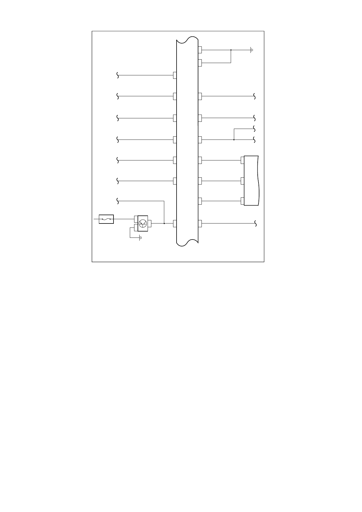
EC
M
组合
仪表
IF25
10A
NL02-2025b
To
Cool
ing
fan
high s
peed
re
lay
To
Cool
ing
fan
low spe
ed r
el
ay1
To
L
ef
t fron
t
comb
ina
ti
on
head
la
mp EF07
To
SRS I
P
15
-8
To
ABSCA13-2
To
a
ir
condi
tionin
g
syst
em re
lay
To
Com
bin
at
ion
ins
tru
men
t
IP02-1
Speed
senso
r
To
C
hip
ant
i-
th
ef
t
modu
le IP24-
8
To
C
hip
ant
i-
th
ef
t
modu
le IP24-
5
To
Com
bina
t
ion
ins
tru
men
t IP02
-17
To
BCM
IP50-3
0
Combi
nat
ion ins
tr
um
ent
To
r
ea
r
defr
ost
IF18
671