Geely Emgrand X7. Manual part - 125


  Главная      Geely     Geely Emgrand X7 - Manual


поиск по сайту            


содержание   ..  122  123  124  125  126  ..


Geely Emgrand X7. Manual part - 125


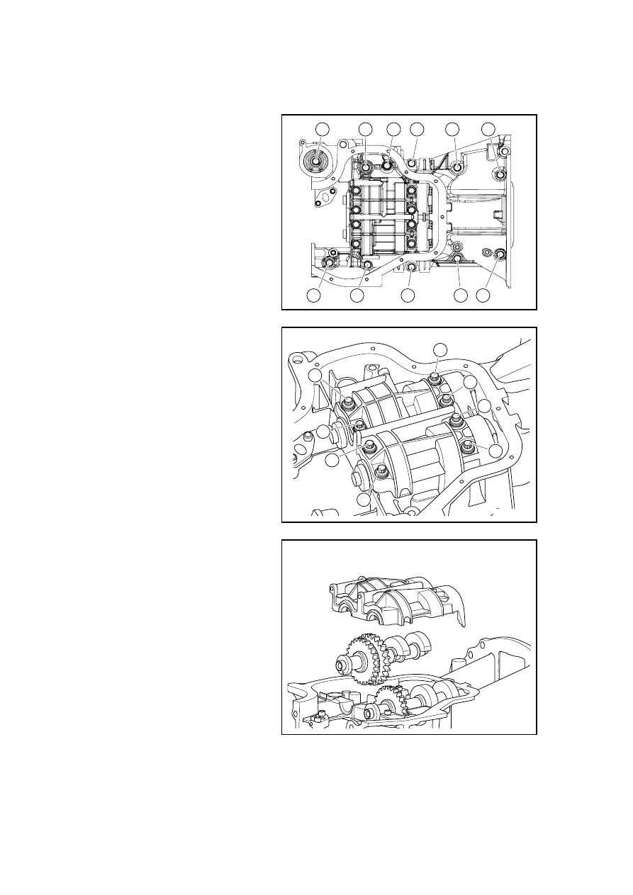
2.6.8.19 Replacement of Balance Shaft 

Dismantlement Procedure 

1.  Dismantle the engine. Refer to 

2.6.8.13 Replacement of Engine. 

2.  Refer to 3.3.6.3 "Replacement of 

Gearbox Assembly" to dismantle 
the gearbox assembly. 

3.  Dismantle oil pan, refer to 2.9.8.3 

Replacement of Oil Pan. 

4.  Dismantle the fixing bolts of 

crankcase according to the 
sequence in the graph. 

5. Dismantle 

the 

crankcase. 

1

2

6

10

7

3

5

9

11

8

4

GC03-0077c

6.  Dismantle the fixing bolts of 

balance shaft bearing cover 
according to the sequence in the 
graph. 

1

7

5

3

2

4

6

8

GC02-0078c

7.  Dismantle balance shaft bearing 

cover. 

8. 

Dismantle balance shaft 
component I. 

GC02-0079c

499

9. 

Dismantle balance shaft 
component II. 

GC02-0080c

10. Dismantle the balance shaft 

bearing. 

GC02-0081c

Inspect balance shaft thrust clearance and balance clearance: 

1.  Inspect balance shaft thrust clearance 

(a)  Install the balance shaft (Refer to the “Balance Shaft Installation”) 

(b)  During moving the balance shaft fore and after, the dial indicator can be used to measure the 

thrust clearance. 

Standard thrust clearance: 0.05mm~0.09mm 

If the thrust clearance can not meet the requirement, the balance shaft housing and bushing 
should be replaced; If necessary, replace the balance shaft. 

2.  Inspect the balance clearance 

(a)  Clean each shaft bushing and neck. 

(b)  Inspect the corrosive pitting and scratching on each shaft bushing and Journal. If damaged, 

replace the shaft bushing. If necessary, replace the balance shaft. 

(c)  Place No.1 and No.2 balance shaft on the crankcase. 

(d)  Place one plastic gap gauge over each Journal. 

(e)  Install the balance shaft housing (refer to the “Installation” section). 

Remarks: Do not rotate the balance shaft. 

500

(f)  Dismantle the balance shaft (refer to the "Dismantle" section) 

(g)  Use the plastic gap gauge to measure the maximum width along the clearance. 

Standard Clearance: 

0.016mm~0.028mm 

Remarks: Totally dismantle the plastic gap gauge after measurement. 

If the clearance does not meet the requirement, replace the shaft bushing. If necessary, replace the 
balance shaft. 

(h)  To replace the bearing, the shaft bushing of the same gauge should be used. If the gauge of 

the balance shaft bushing cannot be identified, the group No. of the Journal aperture 
dimension of the balance shaft housing and the balance shaft bushing group No. can be used 
to choose the correct balance shaft bushing. (Group No. of the Journal aperture dimension of 
the balance shaft housing = Balance shaft bushing group No.) 

Installation Procedure: 

1.  Smear the oil on the internal 

surface of the balance bearing. 

Note: Do not smear the oil on the 
back surface and other contact 
surfaces of the bearing. 

2.  Install the balance shaft bearing 

to the crankshaft housing. 

GC02-0081c

3.  Install crankshaft case body .  

And tighten fixing bolt as per 
orders in the figure t. 

11

10

6

2

5

9

7

3

1

4

8

GC02-0082c

501

4.  Install balance shaft component I.

5.  Install balance shaft component 

II. 

6.  Turn crankshaft until the cylinder 

#1 crank arriving at the bottom. 

Note: as shown in the figure, align 
the No.1 balance shaft and the No.2 
balance shaft, so that the mounting 
hole for reference is located in the 
vertical plane.
 

5.6°

5.6°

安装参照孔

正时标记

GC02-0083c

7.  Install the balance bearing cover 

and tighten the bolts by the order 
shown graph. 

Balance bearing cover bolts should be 
tightened in two steps with the first 
tighten torque of21.5±2N·m,and the 
second tighten torque of 38±3N·m。 

8

2

4

6

7

5

3

1

GC02-0084c

8.  Turn the crankshaft once again to 

make the crankshaft front end 
Woodruff key facing toward the 
top of the engine (at this point, 
piston of the Cylinder #1 is at the 
compression TDC position), and 
then the positional relationship 
between the crankshaft and the 
balance shaft is shown as the 
figure. 

5.6°

5.6°

平衡块分割平面

平衡块分割平面

平衡块分割平面

正时标记

正时标记

GC02-0085c

Timing mark.

Install reference 

hole.

Partition plane of 

balance block 

Timing mark.

Timing mark. 

Partition plane of 

balance block 

Partition plane of 

balance block 

502


содержание   ..  122  123  124  125  126  ..