Geely Emgrand X7. Manual part - 122


  Главная      Geely     Geely Emgrand X7 - Manual


поиск по сайту            


содержание   ..   120  121  122  123  ..


Geely Emgrand X7. Manual part - 122


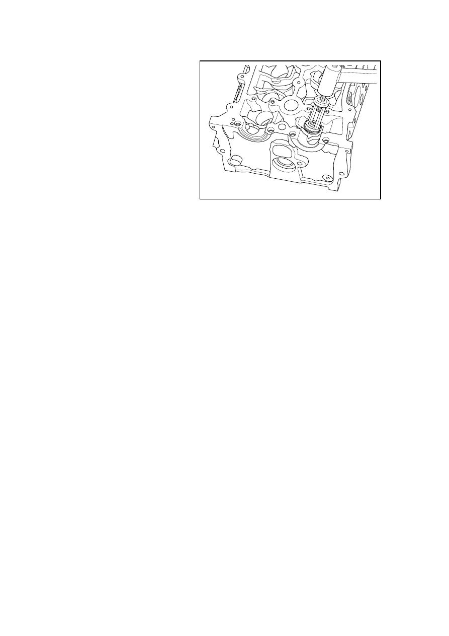
6.  Use a special tool to compress 

the valve springs and install the 
valve spring locking pieces. 

7.  Confirm locking pieces is in 

place. slowly remove the special 
tool with a wood hammer gently 
knock the valve, so that the valve 
is in place. 

Warning: Do not apply excessive 
force, otherwise the valve spring 
might pop up and cause personal 
injury. 

8.  Install the valve lifter. 

9. Install the cylinder hood 

assembly. 

GC02-0058c

487

2.6.8.16 Replacement of Piston, Connecting Rod and Connecting Rod Bearing 

Dismantlement Procedure 

1.  Dismantle the engine. Refer to 

2.6.8.13 Replacement of Engine. 

2.  Refer to 2.6.8.14 "Replacement 

of Cylinder Hood Assembly" to 
dismantle the cylinder hood. 

3.  Dismantle oil pan, refer to 2.9.8.3 

Replacement of Oil Pan. 

4. Dismantle 

the 

crankcase. 

GC02-0062c

5.  Rotate the crankshaft, so that the 

cylinder NO.1 and 4 are at BDC 
positions. Dismantle the cylinder 
NO.1 rod bearing cap bolts. 

6.  Hold the connecting rod bolts 

and take out the Cylinder #1 
connecting rode bearing cap and 
mark the Cylinder #1 position on 
the bearing cap. 

GC02-0063c

7.  Drive #1 cylinder piston and 

connecting rod assembly with a 
wooden stick and mark the 
position of #1 cylinder on the 
piston and connecting rod 
assembly. 

8. Use the same method to 

dismantle the piston connecting 
rod assemblies of cylinders No. 
2, 3 and 4 respectively. 

GC02-0064c


488

Carry out the following inspection procedures prior to the installation of the piston. 

1.  Inspect whether the rod is bent or distorted. If the rod is bent or distorted, replace the 

connecting rod. 

Cross degree: 0.03 (basic length range 
of 100mm) 

Distortion: 0.05 (Basic length range of 
100 mm) 

2. Inspect the connecting rod 

bearings. 

3.    Inspect whether the bottom rod is 

worn. 

4.  Inspect whether the connecting 

rod upper end is scratched. 

5.  Inspect whether there is the 

crankshaft connecting rod 
bearing journal wear and tear. 

6.  Inspect whether the piston is 

scratched, cracked and worn. 

7.  Use the caliper to measure the 

piston pin-hole diameter. 

FE02-0234b

Standard piston pin-hole diameter: 

Group mark 

Piston pin-hole 
diameter (mm) 

A 22.007. 

22.010 

B 22.010. 

22.013 


8.  Use the micrometer to measure 

the piston pin diameter. 

Standard piston pin diameter: 

Group mark 

Piston pin 
diameter (mm) 

A 22.004. 

22.007 

B 22.007. 

22.010 

9.  Inspect the fit clearance between 

piston pin-hole and piston pin. 

Standard value :0 ~ 0 . 
006mm(Metric) 

Note: If the clearance does not meet 

FE02-0235b

489

the requirement, replace the piston 
pin, and replace the piston if 
necessary.
 

11.  Inspect interference fit between 

piston pin and connecting rod. 

12. Inspect engine cylinder block 

hole diameter. 

Standard Value: φ

015

.

0

0

85

+

(Metric) 

13.  Measure the piston diameter with 

the micrometer perpendicular to 
the piston pin-hole with a 
distance to the bottom of the 
piston of 13 mm. 

Standard Value: φ77.75±0.009 

13

GC02-0065c

14.  Inspect the cylinder fit clearance, and subtract the measured piston’s diameter with the 

measured cylinder hole’s diameter. 

Standard clearance: 0.0275mm~0.0575mm 

Note: If the clearance exceeds the range, replace the piston. If necessary, replace the cylinder 
block. 

(To replace the piston, the diameter group No. printed on the piston pin and the piston pin-hole 
diameter group No. printed on the piston can be used to choose the correct piston; the piston 
diameter group No. = piston pin-hole diameter group No. on the piston) 

15.  Select a new set of piston rings, 
use a gap regulator to measure piston 
ring end gap. 

Oil Ring End Clearance: 0.20mm~
0.40mm (Metric) 

Second Compression Ring End 
Clearance: 0.30mm ~ 0.50mm 
(Metric) 

The first compression ring end gap: 
0.20mm-0.40mm (Metric); 16. Check 
the fit clearance of connecting rod 
bearing bush. 

(a)  Place one plastic gap gauge on 

the neck of the connecting rode 
shaft. 

FE02-0236b

(b)  Install the connecting rode cap (connecting rode cap’s frontward mark should face to the 

front end of the engine), and tighten the connecting rode bolts as per the specified torque. 

(c)  Dismantle the connecting rod cap 

(d)  Use the plastic gap gauge to measure the maximum width along the clearance 

490


содержание   ..   120  121  122  123  ..