Freightliner Coronado 132 / 122SD. Manual - part 23
12. Lubricate the O-rings with silicone or lithium
grease and install them in the end cover.
13. Install the desiccant cartridge on the end cover.
Turn the cartridge clockwise until the desiccant
cartridge makes contact with the end cover.
14. Place the desiccant cartridge in a vise, and turn
the end cover clockwise an additional 180 to 225
degrees to fully tighten the desiccant cartridge to
the end cover.
NOTE: Desiccant cartridge torque should not
exceed 50 lbf·ft (68 N·m).
15. Place the housing over the desiccant cartridge
and align the mounting holes with the end cover.
IMPORTANT: Replace, do not reuse the Nylok
nuts on the air dryer cover.
16. Install the 6 bolts, 12 washers, and 6 new Nylok
nuts. Torque the Nylok nuts in a star pattern 17
to 24 lbf·ft (23 to 33 N·m). See
08/09/95
f421383
1
2
3
4
5
9
10
11
12
13
14
15
17
18
19
21
22
23
24
25
10
10
10
10
10
10
6
7
8
8
8
20
16
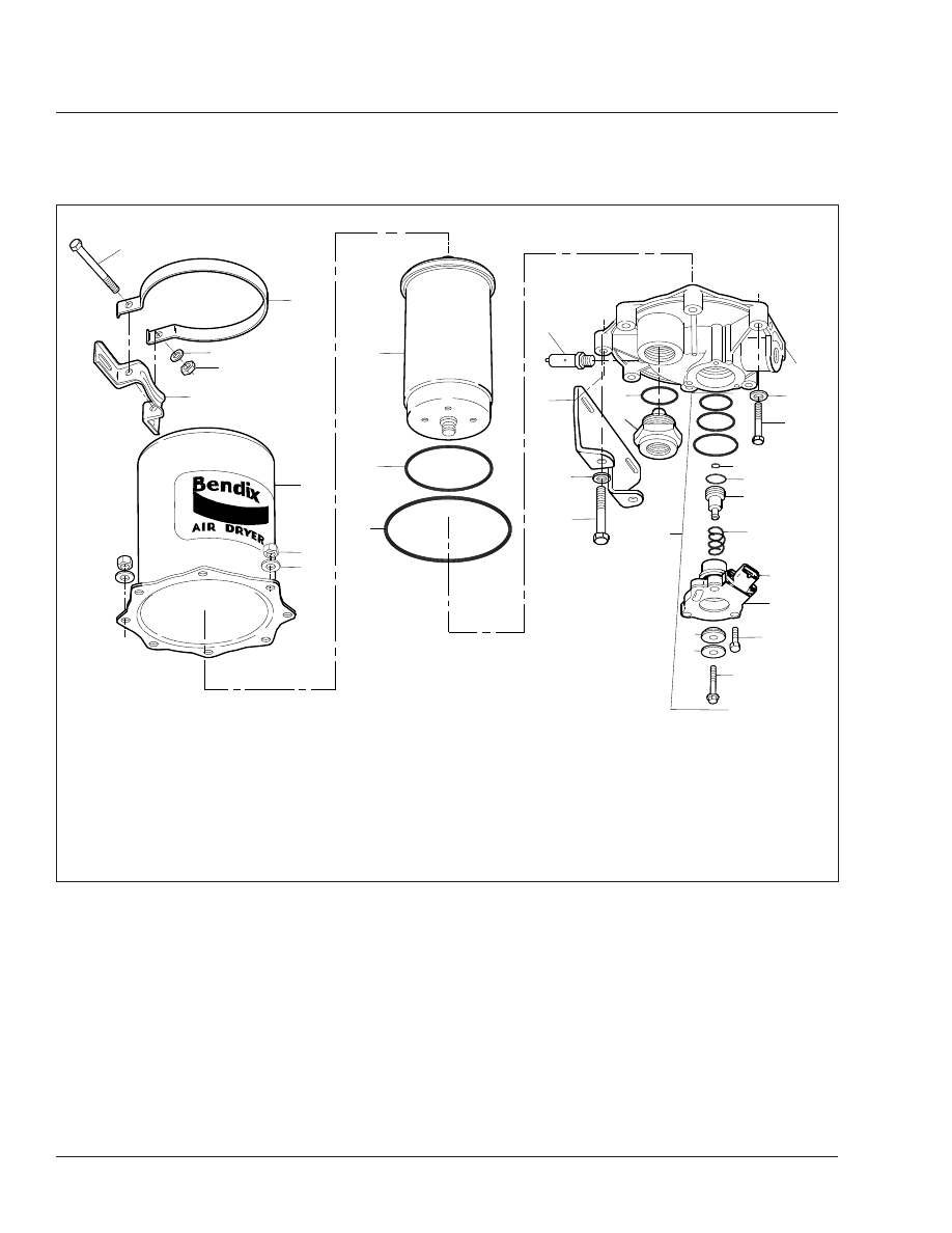
1.
5/16 x 4-1/2 Upper Mounting
Bracket Bolt
2.
Upper Mounting Bracket Strap
3.
Lockwasher
4.
5/16-Inch Nylok Nut
5.
Upper Mounting Bracket
6.
Housing
7.
Nylok Nut
8.
3/8-Inch Special Washer
9.
Desiccant Cartridge
10. O-Ring
11. Safety Valve
12. Lower Mounting Bracket
13. 3/8-Inch Bolt (long)
14. Check Valve Assembly
15. Purge Valve Assembly
16. Purge Valve Capscrew
17. Exhaust Diaphragm
18. Purge Valve
19. 1/4-Inch Tapping Screw
20. Purge Valve Housing
21. Heater and Thermostat
Housing
22. Return Spring
23. Purge Piston
24. 3/8-Inch Bolt
25. End Cover
Fig. 1, AD–9 Air Dryer (exploded view)
Brakes
42
42/2