Freightliner Century Class. Manual - part 30
full lock left and right. Capture the fluid
flowing from the hose in the drain pan.
Add fluid to the reservoir, as needed.
When clean power steering fluid flows
from the hose, remove the plug from the
reservoir and reconnect the steering gear-
to-reservoir hose to the reservoir. Re-
move the jack stands and lower the ve-
hicle.
3.4
With the larger opening at the top, install
a new filter in the reservoir. Install the fil-
ter top plate so its center fits into the
opening at the top of the filter. Install the
filter spring.
3.5
Clean the reservoir cover and O-ring seal.
Inspect the O-ring and the cover for
cracks, deformities, or damage. Replace
the O-ring seal or cover as needed.
3.6
Install the reservoir cover over the
threaded shaft. Apply a slight downward
pressure while installing the rubber
washer and the flanged nut. Tighten the
nut until it is snug.
4.
Use the following procedure for Argosy COEs.
4.1
Remove the clamp that holds the cover
on the reservoir. See
. Remove the
cover.
NOTE: Always replace the power steering
reservoir filter when changing the fluid.
4.2
Lift out the filter spring and the filter top
plate, then remove the filter. It may be
necessary to wiggle the filter to remove it
from its base. Do not use pliers to aid in
removal of the filter; pliers could cause
metal chips to enter the steering system.
Clean the inside of the reservoir using a
lint-free cloth.
IMPORTANT: Do not start the engine while
draining the system.
4.3
Place the disconnected end of the steer-
ing gear-to-reservoir hose in the drain
pan. Raise the front of the vehicle with a
floor jack and support it with jack stands.
Have someone turn the steering wheel to
full lock left and right. Capture the fluid
flowing from the hose in the drain pan.
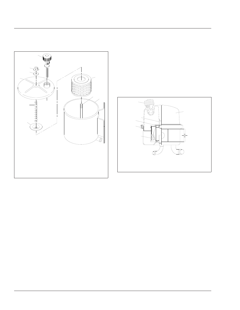
2
3
4
9
8
7
6
5
1
f461070
11/28/95
1.
Vented Fill Cap and
Dipstick
2.
Flanged Nut
3.
Rubber Washer
4.
Reservoir Cover
5.
Filter Spring
6.
Filter Top Plate
7.
Reservoir Filter
8.
Threaded Shaft
9.
Power Steering
Reservoir
Fig. 1, Power Steering Reservoir and Filter, Century
Class Conventional
07/09/98
f461670
1
2
4
5
6
3
1.
Fill Cap
2.
Filter Spring
3.
Filter Top Plate
4.
Clamp
5.
Filter
6.
Reservoir Cover
Fig. 2, Power Steering Reservoir and Filter, Argosy
COE
Steering
46
46/2