Freightliner Century Class. Manual - part 29
 

  Index      Freightliner     Freightliner Century Class - service manual 2016 year


Search            


Content   ..  27  28  29  30   ..


Freightliner Century Class. Manual - part 29


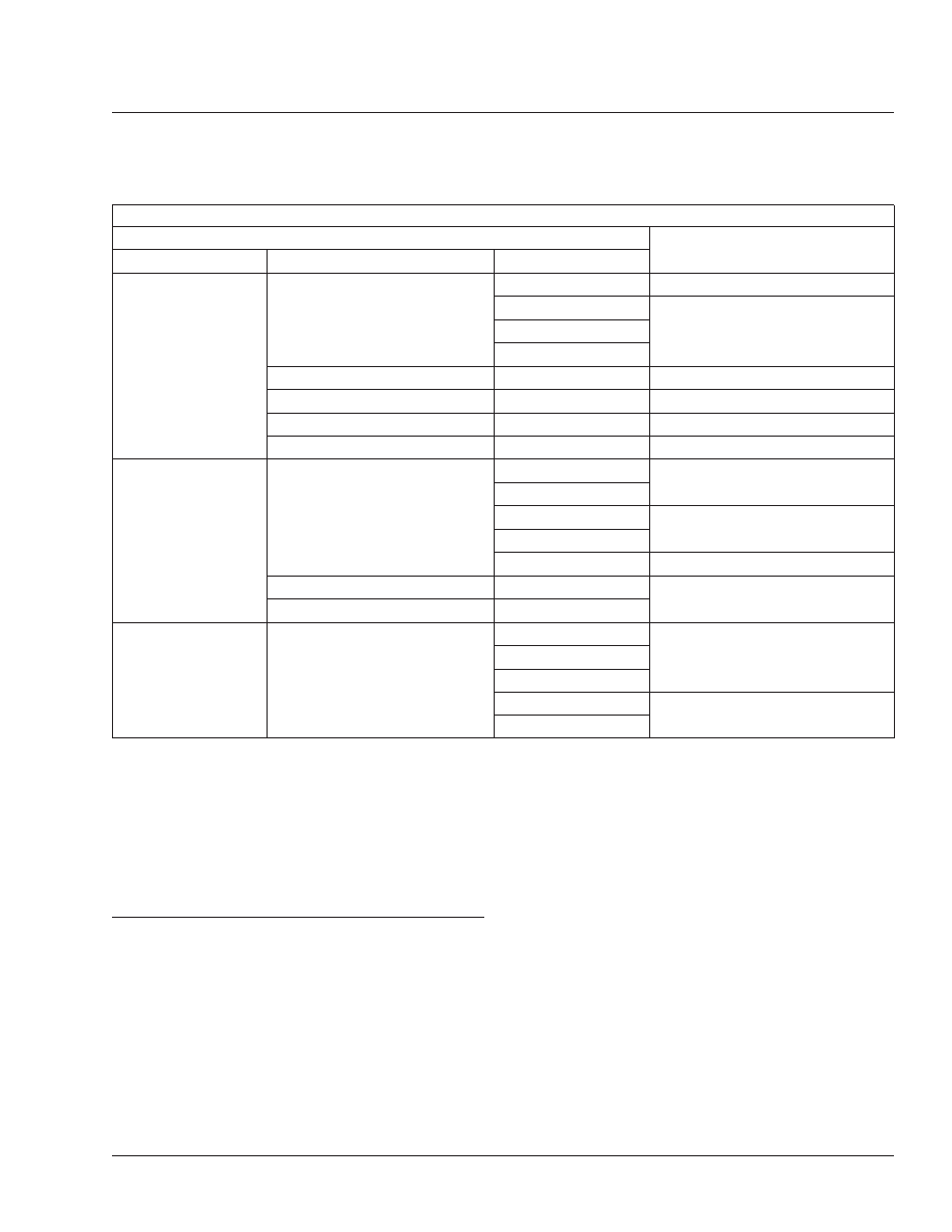
Brake Chamber Stroke Specifications

Chamber

Max Applied Stroke: inch (mm)

Manufacturer

Type

*

Size

Haldex

Standard Stroke

12

1-3/8 (35)

16

1-3/4 (44)

20

24

2-1/2-Inch Extended Stroke

24

2 (51)

3-Inch Extended Stroke

24

2-1/2 (64)

Standard Stroke

30

2 (51)

Long Stroke

30

2-1/2 (64)

Meritor

Standard Stroke

9

Less than 1-1/2 (38)

12

16

Less than 1-3/4 (44)

20

24

Less than 1-7/8 (48)

Long Stroke

24

Less than 2 (51)

Standard Stroke

30

Dana Spicer

Long Stroke

16L

2 (51)

20L

24L

24LS

2-1/2 (64)

30LS

*

Long stroke design is indicated by a tag, or embossing, on the brake chamber.

Specifications are relative to a brake application with 80 to 90 psi (550 to 620 kPa) air pressure in the brake chambers.

If type 36 chamber is used, slack length should be less than 6 inches.

Table 1, Brake Chamber Stroke Specifications

42–11 Versajust Slack Adjuster

Inspection and
Lubrication

IMPORTANT: Perform the Brake Inspection
maintenance operation before lubricating the
slack adjusters.

1.

Visually check for physical damage, such as bro-
ken air lines and broken or missing parts.

2.

Using a quality multipurpose chassis lubricant,
NLGI Grade 2, lubricate the slack adjuster

through the grease fitting until clean lubricant
flows from the grease relief opening in the boot.

3.

Perform the "In Service Inspection."

In Service Inspection

1.

Apply and release the brakes several times while
observing the slack adjuster. The slack adjuster
and brake actuator should move freely, without
binding or interference, and should return to the
full released position. Observe the looseness that
exists between the clevis and adapter bushing
and the yoke and link pins and their mating parts
(clevis, body, link). Replace these parts if loose-

Brakes

42

42/11

ness appears excessive. Make certain the brake
actuator pushrod jam nut is tightened securely.

2.

Inspect the slack adjuster for physical damage,
paying attention to the link, boot, and clevis. If
any components are damaged, repair or replace
them as necessary.

3.

Measure the brake actuator pushrod stroke while
making an 80 to 90 psi (552 to 621 kPa) brake
application. Actuator pushrod strokes should not
exceed the values shown in

Table 2

and

Table 3

To achieve the correct pressure for this

test, build the system pressure up to a 100 psi
(690 kPa). Shut down the engine. Fan the
brakes to attain a 90 to 95 psi (621 to 655 kPa)
reading. Make and hold a full brake application
while the strokes are checked.

Actuator Stroke–Standard Stroke

Brake Actuator Size

Recommended Maximum

Operating Stroke (Inches)

30

2

24

1-3/4

20

1-3/4

16

1-3/4

12

1-3/8

Table 2, Actuator Stroke–Standard Stroke

Actuator Stroke–Long Stroke

Brake Actuator Size

Recommended Maximum

Operating Stroke (Inches)

30 Long Stroke

2-1/2

24 Long

2

24 Long Stroke

2-1/2

20 Long

2

16 Long

2

Table 3, Actuator Stroke–Long Stroke

Brakes

42

42/12

MOP Number

Bellows Replacement, Rack and Pinion Steering Gear . . . . . . . . . . . . . . . . . . . . . . . . . . . . . . . . . . . . . . . 46-07

Drag Link Inspection. . . . . . . . . . . . . . . . . . . . . . . . . . . . . . . . . . . . . . . . . . . . . . . . . . . . . . . . . . . . . . . . 46–01

Drag Link Lubrication . . . . . . . . . . . . . . . . . . . . . . . . . . . . . . . . . . . . . . . . . . . . . . . . . . . . . . . . . . . . . . . 46–05

Power Steering Fluid Level Inspection. . . . . . . . . . . . . . . . . . . . . . . . . . . . . . . . . . . . . . . . . . . . . . . . . . . 46–03

Power Steering Fluid and Filter Changing . . . . . . . . . . . . . . . . . . . . . . . . . . . . . . . . . . . . . . . . . . . . . . . . 46–02

Power Steering Gear Lubrication. . . . . . . . . . . . . . . . . . . . . . . . . . . . . . . . . . . . . . . . . . . . . . . . . . . . . . . 46–04

Rack and Pinion Steering Gear Inspection . . . . . . . . . . . . . . . . . . . . . . . . . . . . . . . . . . . . . . . . . . . . . . . 46–06

Safety Precautions . . . . . . . . . . . . . . . . . . . . . . . . . . . . . . . . . . . . . . . . . . . . . . . . . . . . . . . . . . . . . . . . . 46–00

Steering

46

Index, Alphabetical

46–00 Safety Precautions

Safety Precautions in this section apply to all
procedures within this group.

DANGER

When working on the vehicle, shut down the en-
gine, set the parking brake, and chock the tires.
Before working under the vehicle, always place
jack stands under the frame rails to ensure the
vehicle can not drop. Failure to follow these steps
could result in serious personal injury or death.

46–01 Drag Link Inspection

WARNING

All steering system components are critical for
safe operation of the vehicle. Failure to maintain
the steering system as specified may result in
loss of steering control, which could lead to per-
sonal injury and property damage.

1.

Park the vehicle on a level surface, shut down
the engine, and set the parking brake. Chock the
tires.

2.

Have someone turn the steering wheel from left
to right. Check for movement between the ball
stud end and the pitman arm, and between the
ball stud end and the steering arm.

If the ball stud end is loose, replace the drag
link.

3.

Check the ball stud castle nut for looseness.

If the castle nut is loose, replace it and the cotter
pin. See

Group 00

for torque specifications.

4.

Inspect the boot of the drag link at both the pit-
man arm and the steering arm end for cracks,
splits, or other damage. Replace the boot if
needed.

5.

Grasp the drag link near the pitman arm end,
then push and pull laterally to check for axial
movement in the ball stud end. If it is loose, re-
place the drag link. See Group 46 of the Century
Class Workshop Manual 
for replacement instruc-
tions. If there is 1/8-inch (3-mm) movement or
more, do not drive the vehicle until the drag link
is replaced.

46–02 Power Steering Fluid

and Filter Changing

WARNING

Fill only with approved clean fluid. Failure to use
the proper fluid could cause seal deterioration and
leaks. Fluid leaks could eventually cause loss of
power steering assist. This could lead to an acci-
dent resulting in personal injury or property dam-
age. Wear eye protection when changing the fluid
and filter.

1.

Park the vehicle on a level surface, shut down
the engine, and set the parking brake. Chock the
tires.

2.

Place a drain pan under the power steering res-
ervoir, and remove the steering gear-to-reservoir
return hose at the reservoir. Drain the power
steering fluid into the drain pan and dispose of
the fluid properly. Plug the return line fitting on
the reservoir.

3.

Use the following procedure for Century Class
Conventionals. For Argosy COEs, go to the next
step.

3.1

Use one hand to apply downward pres-
sure to the power steering reservoir
cover. Remove the flanged nut and rub-
ber washer. See

Fig. 1

Remove the

cover.

NOTE: Always replace the power steering
reservoir filter when changing the fluid.

3.2

Lift out the filter spring and the filter top
plate, then remove the filter. It may be
necessary to wiggle the filter to remove it
from its base. Do not use pliers to aid in
removal of the filter; pliers could cause
metal chips to enter the steering system.
Clean the inside of the reservoir using a
lint-free cloth.

IMPORTANT: Do not start the engine while
draining the system.

3.3

Place the disconnected end of the steer-
ing gear-to-reservoir hose in the drain
pan. Raise the front of the vehicle with a
floor jack and support it with jack stands.
Have someone turn the steering wheel to

Steering

46

46/1


Content   ..  27  28  29  30   ..