Freightliner Century Class. Manual - part 18
equalizer bushings. See Group 32 of the
Century Class Trucks Workshop Manual for
instructions.
Freightliner AirLiner Suspension
WARNING
Do not replace individual leaves of a damaged leaf
spring assembly; replace the complete spring as-
sembly. Visible damage (cracks or breaks) to one
leaf causes hidden damage to other leaves. Re-
placement of only the visibly damaged part(s) is
no assurance that the spring is safe. On front
spring assemblies, if cracks or breaks exist in the
two top leaves, a loss of vehicle control could
occur. Failure to replace a damaged spring assem-
bly could cause an accident resulting in property
damage, serious personal injury, or death.
Inspect the forward and rear spring brackets for
wear, cracks, and other damage. If any of these con-
ditions exist, replace the damaged bracket(s). See
Group 32 of the Century Class Trucks Workshop
Manual for instructions.
WARNING
Replace worn, cracked, or damaged spring
brackets. Failure to do so could result in bracket
breakage, possibly leading to loss of vehicle con-
trol and resulting in personal injury or property
damage.
Inspect the crossmember(s) and gussets for wear,
cracks, and other damage. If any of these conditions
exist, replace the damaged parts. See Group 32 of
the Century Class Trucks Workshop Manual for
instructions.
IMPORTANT: Before checking the AirLiner sus-
pension height, make sure there is no load on
the chassis, and the trailer is unhitched.
IMPORTANT: To prevent voiding the warranty
on Barksdale height-control valves, note the fol-
lowing:
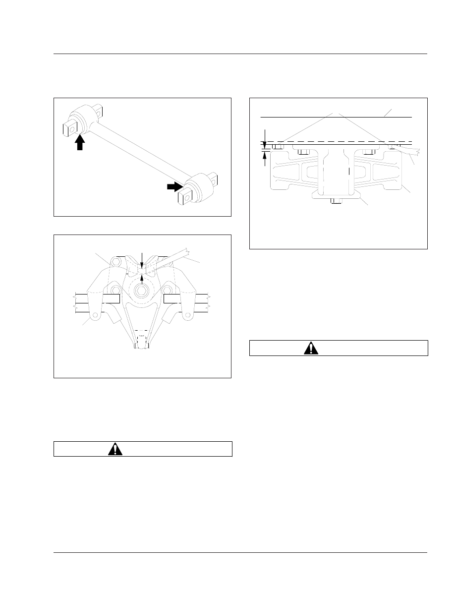
f320021a
05/27/93
Fig. 3, Torque Arm Bushings
f320022a
05/27/93
1
2
3
A
A. Measure the change in gap at this point.
1.
Equalizer Bracket
2.
Equalizer
3.
Pry Bar
Fig. 4, Side View of the Equalizer
f320023a
05/27/93
1
2
3
4
5
A
A. 1/8" (3 mm) Clearance
1.
Frame Fasteners
2.
Frame Rail
3.
Pry Bar
4.
Equalizer
5.
Equalizer Bracket
Fig. 5, Top View of the Equalizer
Suspension
32
32/3