Freightliner Century Class. Manual - part 16


  Index      Freightliner     Freightliner Century Class - service manual 2016 year


Search            


Content   ..  14  15  16  17   ..


Freightliner Century Class. Manual - part 16


9.3

Check the locking mechanism for proper
operation.

If the plungers will not release, check the
air cylinder or plunger adjustment.

If the plungers are loose, check the
plunger adjustment and the plunger
springs for proper compression. Replace
if needed.

9.4

The outboard slider assembly requires no
adjustment. If the plungers are loose, in-
spect and replace locking mechanism
parts as needed.

9.5

The inboard slider is adjustable for frame
width and plunger engagement. For ad-
justment, refer to the fifth wheel installa-
tion instructions.

10. Replace cracked, worn, or damaged parts with

new parts. Replace all loose mounting bolts with
5/8–11 SAE grade 8 bolts, grade C locknuts, and
hardened washers. Do not re-use bolts, nuts,
and washers on fifth wheel mountings.

11. After inspecting the fifth wheel, lubricate all mov-

ing parts with a chassis or multipurpose grease.

09/01/2009

f311099      

A

B

C

D

E

F

G

H

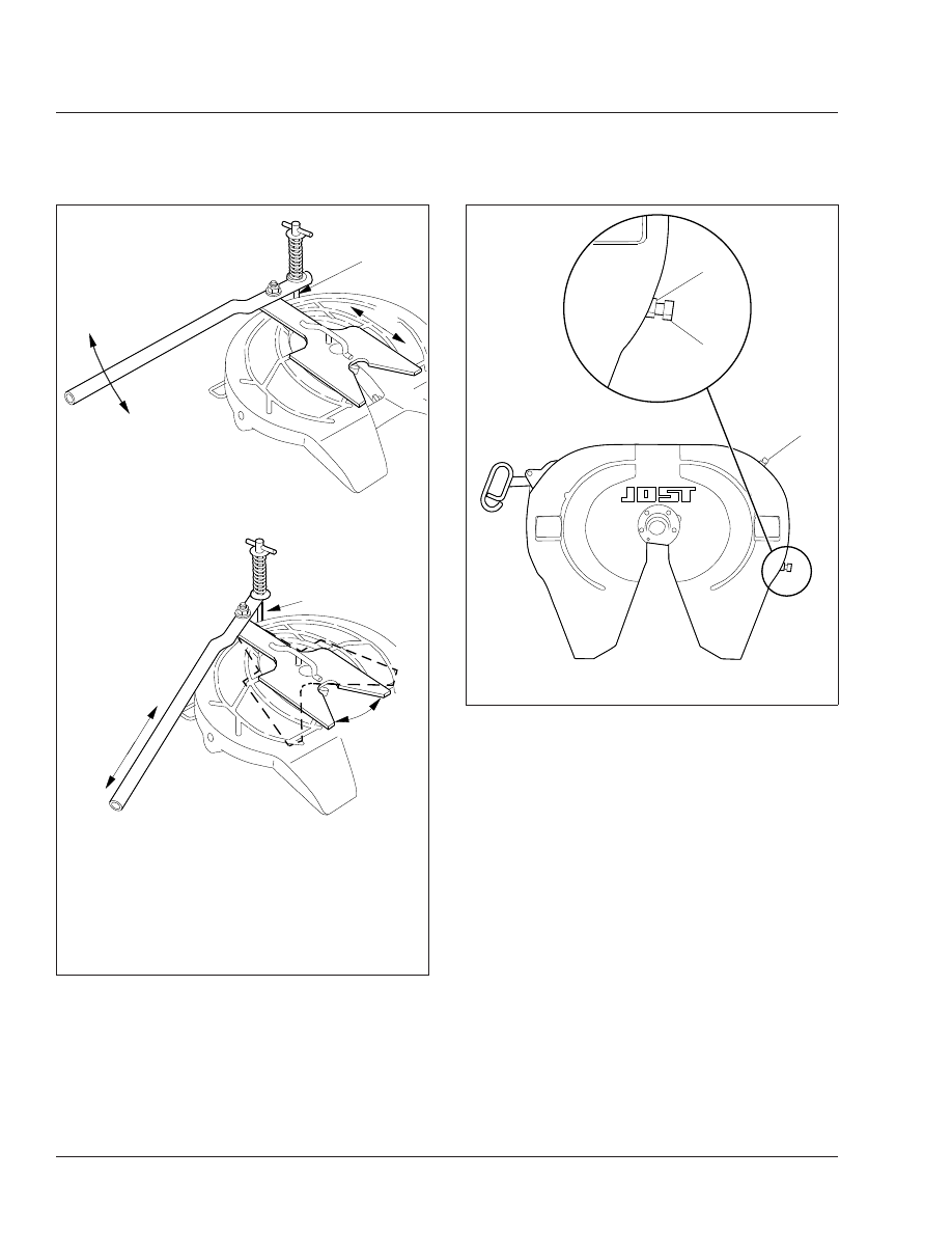
A. Checking for fore/aft play
B. Rotating tester in lock
C. Engage hook
D. Pull/push handle fore/aft.
E. Check for movement of kingpin in lock
F.

Disengage hook

G. Push/pull handle inboard/outboard
H. Rotate lock tester

Fig. 9, Jost Fifth Wheel Adjustment

09/02/2009


3

1

2

f311100

1.

Jam Nut

2.

Adjustment Bolt

3.

Grease Zerk

Fig. 10, Jost Fifth Wheel

Frame and Frame Components

31

31/6

Apply a generous coating of grease to the top
plate to fill the grooves, or depressions, on the
top plate. See

MOP 31–02

for lubrication instruc-

tions.

31–02 Fifth Wheel Lubrication

To maintain proper fifth wheel operation, always lubri-
cate the fifth wheel after an inspection has been
performed.

IMPORTANT: Lubricate the fifth wheel:

• After power washing, or steam cleaning.
• If the vehicle operates in harsh conditions such

as salt spray from road surfaces, or in ex-
tremely dusty environments.

• After any service that requires the removal of

lubrication from the fifth wheel head or compo-
nents.

WARNING

Failure to properly lubricate the fifth wheel could
result in a possible disengagement of the trailer
from the tractor, which could result in personal
injury or property damage.

Fontaine

1.

Tilt the top plate forward (the front of the fifth
wheel is down) and apply grease to each bearing
area through the zerk fittings located on each
side of the top plate just to the front of the
bracket pins. Continue to apply grease until it is
coming out of the back of the bearing. It may be
necessary to raise the rear of the fifth wheel with
a pry bar to open up the pocket slightly and
allow the grease to flow through. A substantial
amount of grease may be required initially to fill
the reservoir.

Tilt the fifth wheel ramps down (the rear of the
fifth wheel is down) and repeat the greasing pro-
cedure. Rock the top plate back and forth sev-
eral times to spread the grease over the bearing
surface.

2.

Inspect the trailer kingpin plate and top surface
of the fifth wheel to make sure each is properly
greased. A liberal coating of grease should be
applied to the complete surfaces of both the

trailer kingpin plate and the top surface of the
fifth wheel.

NOTE: Do not use a lube plate (high density
polyethylene) on top of the fifth wheel or on the
kingpin instead of grease without prior approval
by Fontaine Fifth Wheel. The additional thick-
ness of this material can prevent the proper op-
eration of the fifth wheel and may cause a dan-
gerous condition.

NOTE: Fontaine suggests the use of a Moly
based lubricant such as Mobilgrease XHP 320
or equivalent when applying lubricant to the
locking jaw and wedge.

3.

Lubricate the fifth wheel prior to opening and
closing it. Separate the jaw and wedge with a
screwdriver, and grease the full length of their
mating surfaces. Lubricate the top and bottom
contact surfaces of the jaw and wedge. See

Fig.

1

Open and close the fifth wheel several times

to further distribute the grease.

Lightly oil other moving parts in the fifth wheel.

4.

Apply grease to the top plate. Spread grease all
over the mating surface of the top plate. Be sure
the grease pockets built into the top plates are
full of grease.

Holland FWS1

Apply a heavy coat of grease to the top plate, either
through the grease fittings located on the underside
of the top plate, or by direct application.

Holland FW35

1.

Using a water-resistant lithium-base grease,
grease the top plate.

2.

Using a light oil (such as SAE 10W or 20W
motor oil), lubricate the cam track and pivot. See

Fig. 11

.

3.

Grease the yoke tips, locks, and the release
handle and spring; see

Fig. 12

Grease the

mounting bracket supports through the grease
fittings. A “low temp” grade grease rated for
-30°F (-34°C) or lower such as Cato Oil and
Grease #5213, Craftsman Chemical Co. #LTF 2,
Mystic LP-200, or equivalent is recommended.

Frame and Frame Components

31

31/7

Castloc II and Simplex Series

Use a chassis or multipurpose grease to lubricate the
two grease fittings located on either side of the fifth
wheel top plate. Lubricate the two grease fittings lo-
cated in the grease grooves on the fifth wheel top
plate. Lubricate the two grease fittings located below
the top plate mounting pins. Lubricate the lock
mechanism.

Once the fifth wheel’s moving parts are lubricated,
apply a heavy coat of grease to the top plate, either
through the grease fittings located on the underside
of the top plate, or by direct application. On slide-
mount applications, lubricate the slider lock pockets
and the slider bracket.

Jost

Lubricate the kingpin lock using a hand pump grease
gun through the grease zerk on the skirt of the fifth
wheel; see

Fig. 10

Apply a light oil to all moving

parts. For sliding fifth wheels spray diesel fuel on the
slide path of the base plate.

NOTICE

Do not use a power grease gun. The pressure will
damage the lube line.

If the fifth wheel is not equipped with low-lube plates,
apply a lithium-based grease with extreme pressure
(EP) additive to the trailer contact surface of the fifth
wheel.

NOTE: If the fifth wheel is equipped with low-lube
plates, the top plate only requires lubrication at the
new product break-in stage. The low-lube plates re-
quire no further lubrication.

31–03 Frame Fastener Torque

Check

Frame brackets and components secured with Huck-
bolt® fasteners do not require a torque check, how-
ever, they should be inspected for damage. Frame
brackets and components secured with conventional
bolts and nuts are to be checked at initial mainte-
nance (IM). See

Fig. 13

for pre-EPA07 engine

mounts. Check the torque of frame fasteners to off-
set the effects of "bedding in" (or seating). When
possible, always check the torque of the nut, not the
bolt head. This will give a true torque reading by

12/03/2010

f311136

1

Use a light oil (such as SAE 10W or 20W motor oil) to
lubricate the cam track and pivot.

1.

Cam Plate

Fig. 11, Holland FW35 Fifth Wheel, Oil Lubrication

12/03/2010

f311135

1

2

2

3

3

4

1.

Release Handle and
Spring

2.

Grease Fitting

3.

Yoke Tip

4.

Locks

Fig. 12, Holland FW35 Fifth Wheel, Grease Lubrication

Frame and Frame Components

31

31/8

eliminating bolt body friction. When checking the
torque of frame fasteners, inspect the frame for
cracks and other damage. Set a click-type torque
wrench to the maximum torque of the fastener you
are checking. Apply pressure until the torque wrench
clicks. Do not loosen the bolt to check the torque.
See the applicable torque table in

Group 00

for

torque specifications.

NOTICE

Make sure frame fasteners are properly tightened.
Continued vehicle operation with loose fasteners
could result in bracket or frame damage.

NOTE: Engine supports on vehicles built from
January 2007 do not require checking.

Inspect and check the fasteners at the following
locations:

• Axle Stops
• Engine Trunnion Supports
• Equalizer Brackets
• Exhaust Brackets
• Fifth Wheel Legs
• Fifth Wheel Mountings
• Frame Crossmembers and Gussets
• Front Frame Brackets
• Front Suspension Spring Brackets
• Fuel Tank Brackets
• Radius Rods
• Rear Engine Supports
• Rear Suspension Spring Brackets
• Shock Absorbers
• All Other Frame Fasteners

Any component that shows signs of cracking, or
other damage, must be repaired or replaced. See the
Century Class Trucks Workshop Manual for repair or
replacement information.

1

2

3

2

f220054

4

5

5
8

6

7

9

10

11

12

10

13

03/30/95

1.

Capscrew, 3/4– x 4.5 Inch, Grade 8

2.

Washer, 3/4 Inch

3.

Engine Leg

4.

Capscrew, 1/2–13 x 1.5 Inch, Grade 8

5.

Washer, 1/2 Inch

6.

Upper Isolator

7.

Rear Engine Mount

8.

Nut, 5/16–18

9.

Capscrew, 5/8–11 x 2.5 Inch, Grade 8

10. Washer, 5/8 Inch
11. Lower Isolator
12. Nut, 3/4–10
13. Nut, 5/8–11

Fig. 13, Rear Engine Mount Assembly (pre-EPA07

engines)

Frame and Frame Components

31

31/9


Content   ..  14  15  16  17   ..