Ford Fiesta (1989-1995). Instruction - part 11
inspecting carefully for any wear grooves,
pitting or scoring around the teeth.
21 Refit the thrustwasher with its curved side
facing outwards, followed by the Woodruff
key.
22 Lubricate the oil seal and the crankshaft
sprocket with engine oil, then position the
sprocket on the crankshaft with its thrust face
facing outwards.
23 Using the auxiliary drivebelt pulley and its
retaining bolt, draw the sprocket fully into
position on the crankshaft. Remove the
pulley.
24 Refit the timing belt as described in
Section 8.
10 Camshaft oil seal - renewal
3
1 Remove the camshaft sprocket as
described in the previous Section.
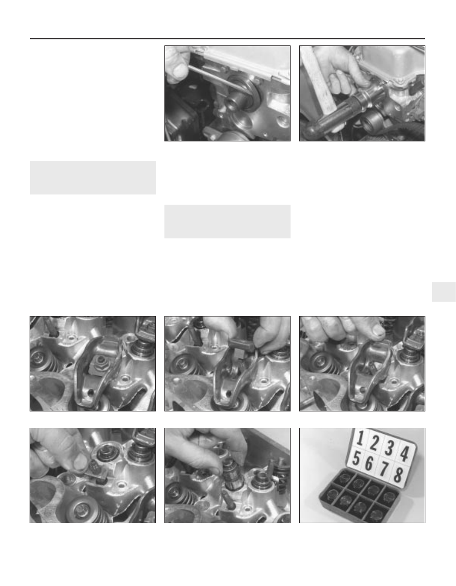
2 The oil seal is now accessible for removal.
Note its direction of fitting, then using a
suitable screwdriver or a tool with a hooked
end to lever and extract the seal from its
housing (but take care not to damage the
housing with the tool) (see illustration).
3 Check that the housing is clean before
fitting the new seal. Lubricate the lips of the
seal and the running faces of the camshaft
with clean engine oil. Carefully locate the seal
over the camshaft, and drive it squarely into
position using a suitable tube or a socket (see
illustration). An alternative method of fitting is
to draw it squarely into position using the old
sprocket bolt and a suitable distance piece.
4 With the seal fully inserted in its housing,
refit the camshaft sprocket as described in
the previous Section.
11 Camshaft, rocker arms and
tappets - removal, inspection
and refitting
3
Removal
1 Disconnect the battery negative (earth) lead
(refer to Chapter 5A, Section 1).
2 Refer to the appropriate earlier Sections in
this Chapter, and remove the timing belt
upper cover and the rocker cover.
3 On carburettor models, refer to Chapter 4A
and remove the fuel pump. On models
equipped with a distributor ignition system,
refer to Chapter 5B and remove the distributor.
On PTE engines, refer to Chapter 4D and
remove the camshaft position sensor.
4 On models equipped with distributorless
ignition system, detach, unbolt and remove
the ignition coil, its support bracket and the
interference capacitor from the end of the
cylinder head, as described in Chapter 5B.
5 Undo the retaining nuts and remove the
guides, rocker arms and spacer plates (see
illustrations). Keep the respective
components in their original order of fitting by
marking them with a piece of numbered tape,
or by using a suitable sub-divided box.
6 Withdraw the hydraulic tappets, again
keeping them in their original fitted sequence.
The tappets should be placed in an oil bath
while removed (see illustrations).
7 Unbolt and remove the lower cover beneath
CVH and PTE engine in-car repair procedures 2B•7
11.5a Undo the rocker arm retaining nut . . .
10.3 Using a socket to tap the camshaft
oil seal into place
11.6b Store tappets in clearly-marked
container filled with oil to prevent oil loss
11.6a Removing a hydraulic tappet
11.5c . . . followed by the rocker arm . . .
11.5b . . . withdraw the guide . . .
11.5d . . . and spacer plate
10.2 Camshaft front oil seal removal
2B
1595Ford Fiesta Remake