Ford Fiesta (1989-1995). Instruction - part 10


  Index      Ford     Ford Fiesta - service and repair instruction 1989-1995 year


Search            copyright infringement  


Content   ..  8  9  10  11   ..


Ford Fiesta (1989-1995). Instruction - part 10


1

General information

How to use this Chapter

This Part of Chapter 2 is devoted to repair

procedures possible while the engine is still
installed in the vehicle, and includes only the
Specifications relevant to those procedures.
Similar information concerning the 1.3 litre
HCS engine, and the 1.6 and 1.8 litre Zetec
engines, will be found in Parts A and C of this
Chapter respectively. Since these procedures
are based on the assumption that the engine
is installed in the vehicle, if the engine has
been removed from the vehicle and mounted
on a stand, some of the preliminary
dismantling steps outlined will not apply.

Information concerning engine/transmission

removal and refitting, and engine overhaul, can
be found in Part D of this Chapter, which also
includes the Specifications relevant to those
procedures.

Engine description

The engine is a four-cylinder, in-line

overhead camshaft type, designated CVH
(Compound Valve angle, Hemispherical
combustion chamber) or PTE (Pent roof, high
Torque, low Emission). The PTE engine was
introduced for 1994 and, apart from
modifications to the cylinder head, camshaft
and intake system, is virtually identical to the
CVH engine it replaces. The engine is
mounted transversely at the front of the
vehicle together with the transmission to form
a combined power unit.

The crankshaft is supported in five split-

shell type main bearings within the cast-iron
crankcase. The connecting rod big-end
bearings are split-shell type, and the pistons
are attached by interference-fit gudgeon pins.
Each piston has two compression rings and
one oil control ring.

The cylinder head is of light alloy

construction, and supports the camshaft in five
bearings. Camshaft drive is by a toothed
composite rubber timing belt, which is driven by
a sprocket on the front end of the crankshaft.
The timing belt also drives the water pump,
which is mounted below the cylinder head.

Hydraulic cam followers (tappets) operate the

rocker arms and valves. The tappets are
operated by pressurised engine oil. When a
valve closes, the oil passes through a port in the
body of the cam follower, through four grooves
in the plunger and into the cylinder feed
chamber. From the chamber, the oil flows to a
ball-type non-return valve and into the pressure
chamber. The tension of the coil spring causes
the plunger to press against the valve, and so
eliminates any free play. As the cam lifts the
follower, the oil pressure in the pressure
chamber is increased, and the non-return valve
closes off the port feed chamber. This in turn
provides a rigid link between the cam follower,
the cylinder and the plunger. These then rise as

a unit to open the valve. The cam follower-to-
cylinder clearance allows the specified quantity
of oil to pass from the pressure chamber, oil only
being allowed past the cylinder bore when the
pressure is high during the moment of the valve
opening. When the valve closes, the escape of
oil will produce a small clearance, and no
pressure will exist in the pressure chamber. The
feed chamber oil then flows through the non-
return valve and into the pressure chamber, so
that the cam follower cylinder can be raised by
the pressure of the coil spring, eliminating free
play until the valve is operated again.

As wear occurs between the rocker arm

and the valve stem, the quantity of oil that
flows into the pressure chamber will be
slightly more than the quantity lost during the
expansion cycle of the cam follower.
Conversely, when the cam follower is
compressed by the expansion of the valve, a
slightly smaller quantity of oil will flow into the
pressure chamber than was lost.

A rotor-type oil pump is mounted on the

timing cover end of the engine, and is driven
by a gear on the front end of the crankshaft. A
full-flow type oil filter is fitted, and is mounted
on the side of the crankcase.

Repair operations possible with
the engine in the car

The following work can be carried out with

the engine in the car:
a)

Compression pressure - testing.

b)

Rocker cover - removal and refitting.

c)

Timing belt - removal, refitting and
adjustment.

d)

Camshaft oil seal - renewal.

e)

Camshaft - removal and refitting.

f)

Cylinder head - removal and refitting.

g)

Cylinder head and pistons - decarbonising.

h)

Crankshaft pulley - removal and refitting.

i)

Crankshaft oil seals - renewal.

j)

Oil filter renewal.

k)

Sump - removal and refitting.

l)

Flywheel - removal, inspection and refitting.

m) Mountings - removal and refitting.
Note: It is possible to remove the pistons and
connecting rods (after removing the cylinder
head and sump) without removing the engine.
However, this is not recommended. Work of
this nature is more easily and thoroughly
completed with the engine on the bench, as
described in Chapter 2D.

2

Compression test -
description and interpretation

2

Refer to Section 2 in Part A of this Chap-

ter.

3

Top Dead Centre (TDC) for
No 1 piston 
- locating

2

Top dead centre (TDC) is the highest point
of the cylinder that each piston reaches as the
crankshaft turns. Each piston reaches its TDC
position at the end of its compression stroke,
and then again at the end of its exhaust
stroke. For the purpose of engine timing, TDC
on the compression stroke for No 1 piston is
used. No 1 cylinder is at the timing belt end of
the engine. Proceed as follows.
Remove the upper timing belt cover as
described in Section 7.
Chock the rear wheels then jack up the
front of the car and support it on axle stands
(see “Jacking and Vehicle Support”).
Undo the retaining bolts, and remove the
cover from the underside of the crankshaft
pulley.
Fit a spanner onto the crankshaft pulley bolt,
and turn the crankshaft in its normal direction
of rotation (clockwise, viewed from the pulley
end) to the point where the crankshaft pulley
timing notch is aligned with the TDC (0) timing
mark on the timing belt cover.
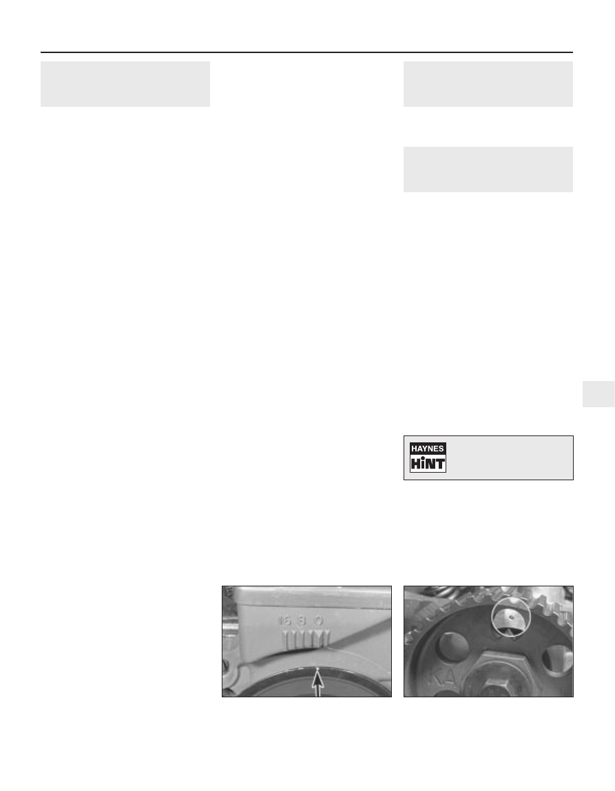
Although the crankshaft is now in top dead
centre alignment, with piston Nos 1 and 4 at
the top of their stroke, the No 1 piston may
not be on its compression stroke. To confirm
that it is, check that the timing pointer on the
camshaft sprocket is exactly aligned with the
TDC mark on the front face of the cylinder
head (see illustrations). If the pointer is not
aligned, turn the crankshaft pulley one further

CVH and PTE engine in-car repair procedures  2B•3

3.6b  Camshaft sprocket timing mark

aligned with the TDC mark on the front

face of the cylinder head

3.6a  Crankshaft pulley notch (arrowed)

aligned with the TDC (0) mark on the

timing belt cover

2B

1595Ford Fiesta Remake

Turning the engine will be
easier if the spark plugs are
removed first - see Chapter 1.

complete turn, and all the markings should
now align.
With the engine set at No 1 piston on TDC
compression, refit the crankshaft pulley cover,
lower the vehicle and refit the upper timing
belt cover.

4

Cylinder head rocker cover -
removal and refitting

2

Removal

Disconnect the battery negative (earth) lead
(refer to Chapter 5A, Section 1).
Remove the air cleaner assembly and air
inlet components as necessary for access as
described in the relevant Part of Chapter 4.
Disconnect the crankcase ventilation hose
from the rocker cover.
Remove the timing belt upper cover as
described in Section 7.
Referring to the relevant Part of Chapter 4
for details, disconnect the accelerator cable
from the throttle linkage and from the adjuster
bracket above the rocker cover. Position the
cable out of the way.
Where applicable, disconnect the choke
cable from the carburettor, referring to
Chapter 4A for details.
Unscrew and remove the rocker cover
retaining bolts and washers, then lift the cover
from the cylinder head. Note that a new
rocker cover gasket will be needed on
refitting.

Refitting

Before refitting the rocker cover, clean the
mating surfaces of both the cylinder head and
the cover.
Locate the new gasket in position, then fit
the cover retaining bolts and washers. Ensure
that the grooves in the plate washers are
facing upwards as they are fitted (see
illustrations)
. Tighten the cover retaining
bolts to the specified torque wrench setting.
Refer to Chapter 4 for details on reconnecting
the accelerator cable, choke cable, air inlet
components and air cleaner (as applicable).
Refit the timing belt cover and reconnect
the battery earth lead.

5

Valve clearances 
general information

It is necessary for a clearance to exist

between the tip of each valve stem and the
valve operating mechanism, to allow for the
expansion of the various components as the
engine reaches normal operating
temperature.

On most older engine designs, this meant

that the valve clearances (also known as
“tappet” clearances) had to be checked and
adjusted regularly. If the clearances were
allowed to be too slack, the engine would be
very noisy, its power output would suffer, and
its fuel consumption would increase. If the
clearances were allowed to be too tight, the
engine’s power output would be reduced, and
the valves and their seats could be severely
damaged.

These engines employ hydraulic tappets

which use the lubricating system’s oil
pressure to automatically take up the
clearance between each camshaft lobe and
its respective valve stem. Therefore, there is
no need for regular checking and adjustment
of the valve clearances. However, it is
essential that only good-quality oil of the
recommended viscosity and specification is
used in the engine, and that this oil is always
changed at the recommended intervals. If this
advice is not followed, the oilways and
tappets may become clogged with particles of
dirt, or deposits of burnt (inferior) engine oil,
so that the system cannot work properly;
ultimately, one or more of the tappets may fail,
and expensive repairs may be required.

On starting the engine from cold, there will

be a slight delay while full oil pressure builds
up in all parts of the engine, especially in the
tappets; the valve components, therefore,
may well “rattle” for about 10 seconds or so,
and then quieten. This is a normal state of
affairs, and is nothing to worry about,
provided that all tappets quieten quickly and
stay quiet.

After the vehicle has been standing for

several days, the valve components may
“rattle” for longer than usual, as nearly all the

oil will have drained away from the engine’s
top-end components and bearing surfaces.
While this is only to be expected, care must
be taken not to damage the engine under
these circumstances - avoid high-speed
running until all the tappets are refilled with oil
and operating normally. With the vehicle
stationary, hold the engine at no more than a
fast idle speed (maximum 2000 to 2500 rpm)
for 10 to 15 minutes, or until the noise ceases.
Do not run the engine at more than 3000 rpm
until the tappets are fully charged with oil and
the noise has ceased.

If the valve components are thought to be

noisy, or if a light rattle persists from the top
end after the engine has warmed up to normal
operating temperature, take the vehicle to a
Ford dealer for expert advice. Depending on
the mileage covered and the usage to which
each vehicle has been put, some vehicles may
be noisier than others; only a good mechanic
experienced in these engines can tell if the
noise level is typical for the vehicle’s mileage,
or if a genuine fault exists. If any tappet’s
operation is faulty, it must be renewed
(Section 11).

6

Crankshaft pulley 
removal and refitting

2

Removal

Disconnect the battery negative (earth) lead
(refer to Chapter 5A, Section 1).
Chock the rear wheels then jack up the
front of the car and support it on axle stands
(see “Jacking and Vehicle Support”).
Unbolt and remove the cover from the
underside of the crankshaft pulley.
Remove the auxiliary drivebelt as described
in Chapter 1.
If timing belt renewal is also intended, set
the engine at TDC as described in Section 3
before removing the crankshaft pulley and
retaining bolt.
To prevent the crankshaft from turning as
the pulley bolt is loosened off, remove the
starter motor as described in Chapter 5A, and
then lock the starter ring gear using a suitable
lever (see illustration).

2B•4 CVH and PTE engine in-car repair procedures

6.6  Using a suitable bar to lock the

flywheel ring gear

4.8b  Rocker cover retaining bolts and

plate washers

4.8a  Fitting a new gasket to the rocker

cover

1595Ford Fiesta Remake

Unscrew and remove the crankshaft pulley
retaining bolt and its washer. Withdraw the
pulley from the front end of the crankshaft
(see illustration). If necessary, lever it free
using a pair of diagonally-opposed levers
positioned behind the pulley.

Refitting

Refit in the reverse order of removal. Tighten
the pulley retaining bolt to the specified torque
setting, and refer to Chapter 1 for details on
refitting the auxiliary drivebelt.
On completion, reconnect the battery
negative lead.

7

Timing belt covers 
removal and refitting

1

Removal

Disconnect the battery negative (earth) lead
(refer to Chapter 5A, Section 1).
Where applicable, undo the two bolts
securing the power steering fluid pipe support
clips and ease the pipe away from the upper
cover.
Undo the two retaining bolts and remove
the upper timing belt cover (see illustration).
Refer to the previous Section for details,
and remove the crankshaft pulley.
Unscrew the two bolts securing the lower
timing belt cover, and remove it (see
illustration)
.

Refitting

Refit in the reverse order of removal.
Tighten the cover retaining bolts to the
specified torque wrench setting.
On completion, reconnect the battery earth
lead.

8

Timing belt - removal, refitting
and adjustment

3

Removal

Referring to the previous Sections for
details, remove the rocker cover, the
crankshaft pulley and the timing belt covers.
Check that the crankshaft is set with the 
No 1 piston at TDC (on its compression
stroke) before proceeding. If necessary, refer
to Section 3 for further details.
To check the timing belt for correct
adjustment, proceed as described in
paragraph 12 below. To remove the belt,
proceed as follows.
Loosen off the two bolts securing the timing
belt tensioner. Using a large screwdriver, prise
the tensioner to one side to release the timing
belt tension. Secure the tensioner in this
position by retightening the bolts (see
illustration)
.
If the original timing belt is to be refitted,
mark it for direction of travel and also the
exact tooth engagement positions on all

sprockets. Slip the belt from the camshaft,
water pump and crankshaft sprockets (see
illustration)
. Whilst the timing belt is
removed, avoid any excessive movement of
the sprockets, otherwise the piston crowns
and valves may come into contact and be
damaged.
If the belt is being removed for reasons
other than routine renewal, check it carefully
for any signs of uneven wear, splitting, cracks
(especially at the roots of the belt teeth) or
contamination with oil or coolant. Renew the
belt if there is the slightest doubt about its
condition. As a safety measure, the belt must
be renewed as a matter of course at the
intervals given in Chapter 1; if its history is
unknown, the belt should be renewed
irrespective of its apparent condition
whenever the engine is overhauled.

Refitting and adjustment

Before refitting the belt, check that the
crankshaft is still at the TDC position, with the
small projection on the belt sprocket front
flange aligned with the TDC mark on the oil
pump housing (see illustration). Also ensure
that the camshaft sprocket is set with its TDC
pointer aligned with the corresponding timing
mark on the cylinder head (see illus-
tration 3.6b)
. If necessary, adjust the
sprockets slightly. As previously mentioned,
avoid any excessive movement of the
sprockets whilst the belt is removed.
Engage the timing belt teeth with the teeth

CVH and PTE engine in-car repair procedures  2B•5

7.5  Lower timing belt cover removal

7.3  Upper timing belt cover removal

6.7  Crankshaft pulley removal

8.7  Sprocket and oil pump housing 

TDC marks in alignment

8.5  Timing belt removal

8.4  Timing belt tensioner retaining bolts

(arrowed)

2B

1595Ford Fiesta Remake

of the crankshaft sprocket, and then pull the
belt vertically upright on its right-hand run.
Keep it taut, and engage it with the teeth of
the camshaft sprocket. If the original belt is
being refitted, check that the belt’s direction
of travel is correct, and realign the belt-to-
sprocket marks made during removal, to
ensure that the exact original engagement
positions are retained. When the belt is fully
fitted on the sprockets, check that the
sprocket positions have not altered.
Carefully manoeuvre the belt around the
tensioner, and engage its teeth with the water
pump sprocket, again ensuring that the TDC
positions of the crankshaft and camshaft 
are not disturbed as the belt is finally 
located.
10 Refit the lower timing belt cover, and
tighten its retaining bolts to the specified
torque setting. Refit the crankshaft pulley, and
tighten its retaining bolt to the specified
torque setting.
11 To take up belt slack, loosen off the
tensioner and move it towards the front of the
car to apply an initial tension to the belt.
Secure the tensioner in this position, then
remove the flywheel ring gear locking device.
12 Rotate the crankshaft through two full
revolutions in (the normal direction of travel),
returning to the TDC position (camshaft
sprocket-to-cylinder head). Check that the
crankshaft pulley notch is aligned with the
TDC (0) mark on the lower half of the timing
belt cover.
13 Grasp the belt between the thumb and
forefinger, at the midway point between the
crankshaft and camshaft sprockets on the
right-hand side. If the belt tension is correct, it
should just be possible to twist the belt
through 90º at this point (see illustration). To
adjust the belt, loosen off the tensioner
retaining bolts, move the tensioner as
required using a suitable screwdriver as a
lever, then retighten the retaining bolts. Rotate
the crankshaft to settle the belt, then 
recheck the tension. It may take two or three
attempts to get the tension correct. On
completion, tighten the tensioner bolts to the
specified torque wrench setting.
14 It should be noted that this setting is
approximate, and the belt tension should be
rechecked by a Ford dealer with the special

tensioner-setting tool at the earliest
opportunity.
15 Refit the starter motor (refer to Chap-
ter 5A).
16 Refit the rocker cover (see Section 4) and
the upper timing belt cover (see Section 7).
17 Refit the auxiliary drivebelt, adjust its
tension as described in Chapter 1, then refit
the crankshaft pulley lower cover.
18 On completion, reconnect the battery
earth lead.

9

Timing belt tensioner and
sprockets 
- removal,
inspection and refitting

3

Tensioner

Set the engine at TDC for No 1 piston on
compression as described in Section 3, then
refer to Section 7 and remove the timing belt
upper cover.
Loosen off the two bolts securing the timing
belt tensioner. Using a large screwdriver, prise
the tensioner to one side to release the timing
belt tension.
Remove the two tensioner bolts, and
withdraw the tensioner from behind the timing
belt.
Check the condition of the tensioner,
ensuring that it rotates smoothly on its
bearings, with no signs of roughness or
excessive free play. Renew the tensioner if in
doubt about its condition.
To refit the tensioner, first check that the
engine is still positioned at TDC for No 1
piston on compression, with both the
camshaft and crankshaft sprocket timing
marks correctly aligned as described in
Section 3.
Refit the tensioner, guiding it in position
around the timing belt, and secure with the
two bolts. Move the tensioner towards the
front of the car, to apply an initial tension to
the belt. Secure the tensioner in this position.
Adjust the timing belt tension as described
in Section 8, paragraphs 12 to 14.
Refit the timing belt upper cover on
completion.

Camshaft sprocket

Set the engine at TDC for No 1 piston on
compression as described in Section 3, then
refer to Section 7 and remove the timing belt
upper cover.
10 Loosen off the two bolts securing the
timing belt tensioner. Using a large
screwdriver, prise the tensioner to one side to
release the timing belt tension. Slip the timing
belt off the camshaft sprocket.
11 Pass a bar through one of the holes in the
camshaft sprocket to prevent the camshaft
from rotating, then unscrew and remove the
sprocket retaining bolt. Note that this bolt
must be renewed when refitting the camshaft
sprocket. Remove the sprocket, noting the
Woodruff key fitted to the camshaft; if the key
is loose, remove it for safekeeping.
12 Check the condition of the sprocket,
inspecting carefully for any wear grooves,
pitting or scoring around the teeth.
13 Install the Woodruff key, then fit the
camshaft sprocket with a new retaining bolt.
The threads of the bolt should be smeared
with thread-locking compound prior to fitting.
Tighten the retaining bolt to the specified
torque wrench setting (see illustrations).
14 Check that the engine is still positioned at
TDC for No 1 piston on compression, with
both the camshaft and crankshaft sprocket
timing marks correctly aligned as described in
Section 3.
15 Slip the timing belt over the camshaft
sprocket, then move the tensioner towards
the front of the car to apply an initial tension to
the belt. Secure the tensioner in this position.
16 Adjust the timing belt tension as
described in Section 8, paragraphs 12 to 14.
17 Refit the timing belt upper cover on
completion.

Crankshaft sprocket

18 Remove the timing belt as described in
Section 8.
19 The crankshaft sprocket can now be
withdrawn. If it is a tight fit on the crankshaft,
a puller or two large screwdrivers can be used
to release its grip. Withdraw the thrustwasher
and the Woodruff key from the crankshaft.
20 Check the condition of the sprocket,

2B•6 CVH and PTE engine in-car repair procedures

9.13b  . . . and tighten the retaining bolt to

the specified torque whilst retaining the

sprocket as shown

9.13a  Refit the camshaft sprocket  . . .

8.13  Checking the tension of the timing

belt

1595Ford Fiesta Remake


Content   ..  8  9  10  11   ..