Dodge Viper SRT-10 (ZB). Manual - part 53


  Index      Dodge     Dodge Viper SRT-10 (ZB) - service repair manual 2005 year


Search            


Content   ..  51  52  53  54   ..


Dodge Viper SRT-10 (ZB). Manual - part 53


HOSE CLAMPS

DESCRIPTION

The cooling system uses constant tension spring

type hose clamps. If a spring type clamp replacement
is necessary, replace with the original Mopar

t equip-

ment spring type clamp.

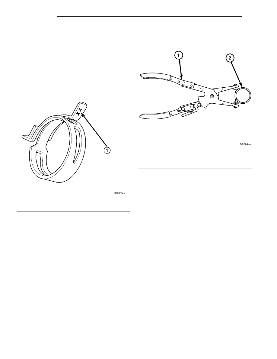
CAUTION: A number or letter is stamped into the
tongue of constant tension clamps. If replacement
is necessary, use only a original equipment clamp
with matching number or letter (Fig. 17).

The constant tension type hose clamps maintain

constant clamping force on the hose connections as
the temperature of the cooling system rises and falls.
Worm gear type hose clamps may not have sufficient
clamping

force

in

colder

weather

conditions

if

installed during warm weather.

To remove a spring type hose clamp, use Special

Tool 8495 Hose Clamp Pliers, or equivalent, (Fig. 18)
to compress the hose clamp.

COOLING SYSTEM HOSES

DESCRIPTION

If cooling system hose replacement is necessary,

replace with the original Mopar

t equipment hoses

(Fig. 19).

RADIATOR FAN

DESCRIPTION

The hydraulic cooling fan is integral to the fan

shroud and is located between the radiator and the
engine. The power steering pump supplies hydraulic
fluid and pressure to rotate the cooling fan blade,
while the electrical part of the fan is controlled by
the PCM.

The hydraulic fan drive (motor) consists of the

three major following components:

• Steering flow control valve

• Fan control valve

• Two stage G-rotor hydraulic drive
The hydraulic fan and drive is not serviceable sep-

arately. Therefore any failure of the fan blade,
hydraulic fan drive or fan shroud requires replace-
ment of the fan module because the fan blade and
hydraulic fan drive are matched and balanced as a
system and servicing either separately would disrupt
this balance.

Fig. 17 Spring Clamp Size Location

1 - SPRING CLAMP SIZE LOCATION

Fig. 18 Hose Clamp Pliers

1 - SPECIAL TOOL 8495 HOSE CLAMP PLIERS
2 - HOSE CLAMP

7 - 20

ENGINE

ZB

For hydraulic fluid routing information refer to

(Fig. 20).

CAUTION: Do not attempt to service the hydraulic
cooling fan or fan drive separately. Replace the
cooling fan as an assembly. Failure to do so may
cause severe damage to the hydraulic cooling fan
assembly.

OPERATION

HYDRAULIC FAN STRATEGY

The hydraulic cooling fan is controlled by the PCM.

A PWM (Pulse With Modulated) signal from the PCM
controls the fan from 0 to 100% of the available fan
speed. There are two inputs to the PCM that deter-
mine what speed percentage of fan is required by the
vehicle. These inputs are:

• Engine Coolant Temperature

• A/C System Pressure
By monitoring these two parameters, the PCM can

determine if cooling airflow is required. If airflow is
required, the PCM will slowly ramp up (speed up)
the fan speed until the parameter(s) are under con-
trol. Once the temperature or pressure is reduced to
within operating parameters the fan will ramp up,
ramp down, or hold its speed to maintain the temper-
ature / pressure requirements.

NOTE: Even if the PCM is not requesting fan on
operation the fan blade will usually spin between
100 and 500 RPM when the vehicle is at idle. This is
due to a controlled minimum oil flow requirement
through the fan drive motor.

Fig. 19 Cooling System Hoses

1 - COOLANT BOTTLE INLET HOSE
2 - HEATER SUPPLY AND RETURN HOSE ASSY.
3 - OIL COOLER RETURN HOSE

4 - LOWER RADIATOR HOSE
5 - UPPER RADIATOR HOSE

ZB

ENGINE

7 - 21

RADIATOR FAN (Continued)

ACTIVATING THE HYDRAULIC FAN WITH THE
DRBIII

T

Under the Engine Systems test heading, there is a

subheading. “Hydraulic fan solenoid test”, that has
the selections, on /off. Activating the fan with the
DRBIII

t will run the fan at 100% duty cycle, which

will help troubleshoot any system problems, and also
help with the deaeration procedure.

NOTE: Engine must be running to activate the fan
with the DRBIII

T

.

RADIATOR COOLING FAN HYDRAULIC FLUID PATH

Hydraulic fluid is pumped through the power

steering pump, from the pump the fluid travels
though a high pressure delivery line to the fan drive
motor. As fluid is diverted through the G-rotors, rota-
tional motion is created as fluid moves from the high-
pressure (inlet) side of the motor to the low-pressure
(outlet) side. Fluid exiting the drive motor is divided
into two paths. Path one continues through a high

pressure delivery line to the vehicles steering gear to
provide steering assist. Path two sends fluid back to
the power steering pump through a low pressure
line. Fluid exits the steering gear under low pressure
and travels through a low pressure line to the power
steering fluid cooler to be cooled before being
returned back the the power steering fluid reservoir
(Fig. 20).

NOTE: There is a steering flow control valve located
in the fan drive motor. This valve operates like the
flow control valve found in the typical power steer-
ing pump. Because of the design of the valve steer-
ing assist can not be affected by the radiator
cooling fan even during fan drive failure.

REMOVAL

(1) Disconnect throttle body air inlet hose, remove

air cleaner housing assembly (Refer to 9 - ENGINE/
AIR INTAKE SYSTEM - REMOVAL).

(2) Raise vehicle on hoist.

Fig. 20 Hydraulic Fan Fluid Flow Circuit

1 - POWER STEERING RESERVOIR
2 - POWER STEERING PUMP
3 - HYDRAULIC FAN DRIVE ASSEMBLY
4 - FAN BLADE

5 - HYDRAULIC FAN CONTROL SOLENOID
6 - POWER STEERING OIL COOLER
7 - STEERING GEAR

7 - 22

ENGINE

ZB

RADIATOR FAN (Continued)

(3) Remove push pins from lower air dam that con-

nect to radiator fan shroud (Fig. 21).

(4) Lower vehicle.
(5) Disconnect the electrical connector for the fan

control solenoid (Fig. 22).

NOTE: The hydraulic fan drive is driven by the
power steering pump. When removing lines or
hoses from fan drive assembly use a drain pan to
catch any power steering fluid that may exit the fan
drive or the lines and hoses.

NOTE: When ever the high pressure line fittings are
removed from the hydraulic fan drive the O-rings
must be replaced.

(6) Disconnect two high pressure lines at hydraulic

fan drive (Fig. 22). Remove and discard o-rings from
line fittings.

(7) Disconnect low pressure return hose at hydrau-

lic fan drive (Fig. 22).

(8) Unclip

hydraulic

lines

from

radiator

fan

shroud.

(9) Remove the radiator fan mounting fasteners

(Fig. 23).

(10) Remove the shroud and fan drive from vehi-

cle.

INSTALLATION

CAUTION: There is an external ground wire con-
nected to the hydraulic fan drive located at the elec-
trical connector on the fan assembly. This ground
MUST remain connected at all times. Failure to
ensure ground wire is connected when engine is
operating can cause severe damage to the PCM.

(1) Position fan drive and shroud in vehicle.
(2) Install radiator fan mounting fasteners (Fig.

23). Tighten fasteners to 5 N·m (45 in. lbs.).

NOTE: Whenever the high pressure line fittings are
removed from the hydraulic fan drive the o-rings
located on the fittings must be replaced.

(3) Lubricate the o-rings on the fittings with power

steering fluid then connect inlet and outlet high pres-
sure lines to fan drive (Fig. 22). Tighten pressure
inlet line to 47 N·m (35 ft. lbs.). Tighten pressure
outlet line to 29 N·m (21 ft. lbs.).

(4) Connect low pressure return hose to fan drive

(Fig. 22).

(5) Clip hydraulic lines to radiator fan shroud.
(6) Connect electrical connector for hydraulic fan

control solenoid.

(7) Raise vehicle on hoist.

Fig. 21 Air Dam

1 - PUSH PIN(S)
2 - AIR DAM
3 - BRAKE COOLING AIR DUCT
4 - RADIATOR FAN SHROUD

Fig. 22 Hydraulic and Electrical Connections

1 - LOW PRESSURE RETURN HOSE
2 - HIGH PRESSURE LINE (OUTLET)
3 - HIGH PRESSURE LINE (INLET)
4 - FAN CONTROL SOLENOID CONNECTOR

ZB

ENGINE

7 - 23

RADIATOR FAN (Continued)


Content   ..  51  52  53  54   ..