Dodge Viper SRT-10 (ZB). Manual - part 21


  Index      Dodge     Dodge Viper SRT-10 (ZB) - service repair manual 2005 year


Search            


Content   ..  19  20  21  22   ..


Dodge Viper SRT-10 (ZB). Manual - part 21


center of the upper ball joint (or strut) and the lower
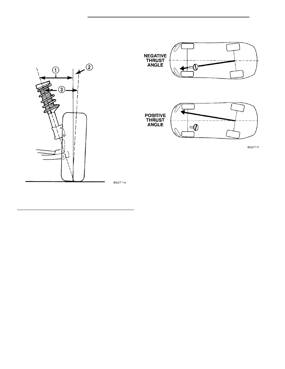
ball joint (Fig. 5). S.A.I. is built into the vehicle and
is not an adjustable angle. If S.A.I. is not within
specifications, a bent or damaged suspension compo-
nent may be the cause.

INCLUDED ANGLE (I.A.)

Included angle is the sum of the S.A.I. angle plus

or minus the camber angle, depending on whether or
not the wheel has positive or negative camber (Fig.
5). If camber is positive, add the camber angle to the
S.A.I angle. If camber is negative, subtract the cam-
ber angle from the S.A.I. angle. Included angle is not
adjustable, but can be used to diagnose a frame mis-
alignment or bent suspension component (spindle,
strut).

THRUST ANGLE

Thrust angle is the averaged direction the rear

wheels are pointing in relation to the vehicle’s center
line (Fig. 6). The presence of negative or positive
thrust angle causes the rear tires to track improperly
to the left or right of the front tires (dog tracking).

• Negative thrust angle means the rear tires are

tracking to the left of the front tires.

• Positive thrust angle means the rear tires are

tracking to the right of the front tires.

Improper tracking can cause undue tire wear, a

lead or pull and a crooked steering wheel. Excessive
thrust angle can usually be corrected by adjusting

the rear wheel toe so that each wheel has 1/2 of the
total toe measurement.

CURB HEIGHT

There are two different vehicle suspension heights

measured on this vehicle. They are Curb Height and
Design Height. Curb height is the vehicle’s height
when:

• it has a full tank of fuel;

• all fluids are filled to their proper levels; and

• no passengers or additional weight have been

added to the vehicle.

For information on design height, (Refer to 2 -

SUSPENSION/WHEEL ALIGNMENT - DESCRIP-
TION - DESIGN HEIGHT).

DESIGN HEIGHT

There are two different vehicle suspension heights

measured on this vehicle. They are Curb Height and
Design Height. For information on curb height,
(Refer to 2 - SUSPENSION/WHEEL ALIGNMENT -
DESCRIPTION - CURB HEIGHT).

Generally speaking, design height is the same as

curb, except for the addition of passengers loaded
into the driver and passenger seats. In other words,
design height of this vehicle is somewhat lower than
curb height.

The vehicle is set to design height during factory

production. At

this

height

all

rubber

bushing-

mounted components of the vehicle’s suspension sys-
tem are tightened and torqued to specification.

Fig. 5 S.A.I. and I.A.

1 - S.A.I.
2 - CAMBER
3 - I.A.

Fig. 6 Thrust Angle

2 - 58

WHEEL ALIGNMENT

ZB

WHEEL ALIGNMENT (Continued)

CAUTION: Design height must be correctly set after
any rubber bushing-mounted suspension compo-
nent is installed on the vehicle. Rubber bushing-
mounted suspension component fasteners must be

tightened and torqued with the vehicle at the cor-
rect

design

height.

Otherwise,

curb

height

is

affected and the handling characteristics of the
vehicle are jeopardized.

DIAGNOSIS AND TESTING - SUSPENSION AND STEERING

CONDITION

POSSIBLE CAUSES

CORRECTION

FRONT END NOISE

1. Loose Or Worn Front Wheel
Bearing.

1. Replace Wheel Bearing.

2. Loose Or Worn Shock Absorber
Mounting Hardware Or Shock
Absorber.

2. Tighten Shock Absorber Mounting Bolts
To Specified Torque Or Replace Shock
Absorber If Required.

3. Loose Steering Gear Mounting
Bolts.

3. Tighten Steering Gear Mounting Bolts
To Specified Torque.

4. Worn Upper Or Lower Control
Arm Bushings.

4. Replace Required Control Arm Bush-
ings.

5. Loose Suspension Component
Mounting Bolts.

5. Inspect All Suspension Component
Mounting Bolts For Looseness And Tighten
To Specified Torque If Required.

EXCESSIVE PLAY IN
STEERING LINKAGE

1. Loose Or Worn Front Wheel
Bearing.

1. Replace Wheel Bearing.

2. Loose Or Worn Steering Column
Shaft Coupling.

2. Replace Steering Column Shaft Cou-
pling.

3. Loose Steering Gear Mounting
Bolts.

3. Tighten Steering Gear Mounting Bolts
To Specified Torque.

4. Worn Steering Gear Isolator
Bushings.

4. Replace Steering Gear Isolator Bush-
ings

5. Worn Tie Rod End Ball Studs.

.5. Replace Tie Rod End.

6. Loose Lug Nuts.

6. Verify Wheel Lug Nuts Are Tightened To
Specified Torque.

FRONT WHEEL SHIMMY

1. Loose Or Worn Front Wheel
Bearing.

1. Replace Wheel Bearing.

2. Tire/Wheel Out Of Balance.

2. Balance Front Wheel And Tire Assem-
blies Or Replace If Required.

3. Uneven Tire Tread Wear Or
Excessively Worn Tire Tread.

3. Replace Tires.

4. Worn Tie Rod End Ball Studs.

4. Replace Tie Rod End.

5. Worn Upper Or Lower Control
Arm Bushings.

5. Replace Control Arm Bushing.

6. Loose Or Worn Upper Or Lower
Control Arm Ball Joint.

6. Replace Upper Control Arm Assembly
Or Lower Ball Joint.

7. Incorrect Front Wheel Alignment
(Particularly Caster).

7. Verify Vehicle Alignment And Adjust To
Preferred Specifications As Required.

VEHICLE INSTABILITY

1. Low Or Uneven Tire Air Pres-
sure.

1. Inflate All Tires To The Recommended
Pressure.

2. Loose Front Or Rear Wheel
Bearings.

2. Inspect Wheel Bearings For Looseness
And Replace As Required.

ZB

WHEEL ALIGNMENT

2 - 59

WHEEL ALIGNMENT (Continued)

CONDITION

POSSIBLE CAUSES

CORRECTION

3. Broken Or Weak Coil Spring(s).

3. Replace Coil Spring(s).

4. Shock Absorber Not Functioning
Correctly

4. Replace Shock Absorber.

. 5. Excessive Friction In Steering
Gear.

5. Replace Steering Gear.

6. Excessive Friction In Steering
Column Shaft Coupling.

6. Replace Intermediate Steering Shaft.

7. Loose Or Worn Upper Or Lower
Control Arm Isolator Bushings.

7. Inspect Control Arm Bushings For Wear
Or Looseness And Replace As Required.

8. Incorrect Front Or Rear Wheel
Alignment.

8. Verify Vehicle Alignment And Adjust To
Preferred Specifications As Required.

EXCESSIVE FORCE
REQUIRED TO STEER
VEHICLE

1. Low Or Uneven Tire Air Pres-
sure.

1. Inflate All Tires To The Recommended
Pressure.

2. Loose, Worn Or Glazed Power
Steering Pump Drive Belt.

2. Tighten Or Replace The Power Steering
Pump Drive Belt As Required.

3. Low Fluid Level In Power Steer-
ing System.

3. Fill The Power Steering System To The
Required Fluid Level.

4. Lack Of Assist From Power
Steering Pump.

4. Test Power Steering Pump And Replace
If Required.

5. Upper Or Lower Ball Joints
Require Lubrication.

5. Properly Lubricate Ball Joints Or
Replace If Required.

6. Tie Rod Ends Require Lubrica-
tion.

6. Properly Lubricate Tie Rod Ends Or
Replace If Required

7. Steering Gear Malfunction.

.7. Replace Steering Gear.

8. Incorrect Front Wheel Alignment
(Particularly Caster).

8. Verify Vehicle Alignment And Adjust To
Preferred Specifications As Required.

VEHICLE PULLS TO ONE
SIDE

1. Low Or Uneven Tire Air Pres-
sure.

1. Inflate All Tires To The Recommended
Pressure.

2. Radial Tire Lead (See Tire Ser-
vice).

2. Inspect Tires For A Condition Of Radial
Tire Lead And Replace Tires As Required.

3. Brake Caliper Hanging Up.

3. Diagnose Vehicle For Condition Of
Brake Pull And Correct As Required.

4. Broken Or Weak Rear Spring.

4. Replace Rear Coil Spring.

5. Loose Or Worn Suspension
Component Bushings.

5. Inspect The Suspension Components
For Worn Or Lose Bushings And Replace
The Bushing Or Component As Required.

6. Incorrect Front Wheel Alignment
(Either Caster Or Camber).

6. Verify Vehicle Alignment And Adjust To
Preferred Specifications As Required.

2 - 60

WHEEL ALIGNMENT

ZB

WHEEL ALIGNMENT (Continued)

STANDARD PROCEDURE

PRE-WHEEL ALIGNMENT INSPECTION

Before starting a wheel alignment on this vehicle,

the following inspection and necessary corrections
must be completed to ensure proper wheel alignment.

(1) Be sure the fuel tank is full of fuel. If the tank

is not full, the reduction in weight will affect the
height of the vehicle and the alignment specifica-
tions.

(2) The passenger and luggage compartments of

the vehicle should be free of any load that is not fac-
tory equipment.

(3) Check the tires on the vehicle. The tires are to

be inflated to the recommended air pressure. All tires
must be the correct size and in good condition, with
approximately the same tread wear. (Refer to 22 -
TIRES/WHEELS/TIRES - DESCRIPTION)

(4) Check the front and rear wheels for excessive

radial and lateral runout, and imbalance. (Refer to
22 - TIRES/WHEELS - DIAGNOSIS AND TESTING)
(Refer to 22 - TIRES/WHEELS - STANDARD PRO-
CEDURE)

(5) Inspect the front and rear hub and bearing

assemblies for wear.

(6) Inspect all suspension components for wear

and noise. Check components for correct torque.

(7) Inspect the rubber bushings on all suspension

components for signs of wear or deterioration.

(8) Inspect the control arm ball joints and steering

linkage for leaking seals, looseness, roughness, bind-
ing or a sticking condition.

(9) Inspect front and rear shock assemblies for

leaks or any sign of damage. Jounce front and rear of
vehicle to determine if the shock absorbers dampen
vehicle motion properly.

CURB HEIGHT MEASUREMENT

NOTE: This procedure is designed to be performed
with original factory wheels installed. Non-OEM
wheels may cause inaccurate measurement.

(1) Verify vehicle fuel tank is full of fuel. If tank is

not full of fuel, reduction in weight will affect height
of vehicle and design height measurement.

(2) Remove any load within passenger and luggage

compartments that is not factory equipment.

(3) Place vehicle on wheel alignment rack or

drive-on lift per equipment manufacturer’s recom-
mendations.

(4) Check all tires for proper inflation pressure

and adjust as necessary.

NOTE: In order to get an accurate rear height mea-
surement it is necessary to remove the belly pan.

(5) Remove belly pan from frame. (Refer to 23 -

BODY/EXTERIOR/BELLY PAN - REMOVAL)

(6) Place Adapter, Special Tool 8897, over smaller

end of one of two Suspension Height Gages, Special
Tool 6914 (Fig. 7) (Fig. 8), aligning adapter locating
pin with notch in gage end.

(7) Tighten adapter thumb screw.

NOTE: The height gage with the adapter attached to
it is now the height gage to be used on the front
suspension.

NOTE: In order to achieve an accurate vehicle
height measurement, it is absolutely necessary to
position the height gages on the inner rim flange at
the very bottom of the wheel. That way the top sur-
face of each gage is parallel front-to-rear with bot-
tom surface of the frame rails.

(8) Install front and rear Suspension Height Gages

on vehicle (Fig. 9) (Fig. 10). Ensure that gages are
correctly attached to inner rim flange at very base of
each wheel.

(9) Jounce vehicle several times, each time paying

special attention to release vehicle at very bottom of
jounce cycle. This will allow suspension to settle to
correct height.

(10) Measure

and

record

vehicle’s

front

curb

height. Measure distance between top of Suspension
Height Gage and each frame rail at forward edge of
gage (Fig. 12). This is the nearest point to the Prin-
ciple Locating Point (PLP) hole.

(11) Measure and record vehicle’s rear curb height.

Measure distance between top of Suspension Height
Gage and each frame rail at forward edge of gage
(Fig. 13). This is the nearest point to the PLP hole.

(12) Compare recorded measurements to specifica-

tions (Refer to 2 - SUSPENSION/WHEEL ALIGN-
MENT - SPECIFICATIONS). If vehicle’s curb height
does not meet specifications, one of the following
could be at fault:

(a) A suspension component could be damaged or

worn excessively. Inspect all suspension compo-
nents for damage or wear paying special attention
to the following:
• Coil springs

• Shock assembly mounting bushings

• Upper and lower control arm mounting bushings

• Front and rear sway bar

• Possible damage to the vehicle’ frame which

affects the mounting location of any suspension com-
ponent. Following inspection and any correction
made, measure vehicle’s design height. (Refer to 2 -
SUSPENSION/WHEEL ALIGNMENT - STANDARD
PROCEDURE

-

DESIGN

HEIGHT

MEASURE-

MENT)

ZB

WHEEL ALIGNMENT

2 - 61

WHEEL ALIGNMENT (Continued)


Content   ..  19  20  21  22   ..