Dodge Dakota (R1). Manual - part 468


  Index      Dodge     Dodge Dakota (R1) - service repair manual 2000 year


Search            


Content   ..  466  467  468  469   ..


Dodge Dakota (R1). Manual - part 468


VALVE TIMING

STANDARD PROCEDURE - CHECKING TIMING
CHAIN WEAR

NOTE: Timing chain tensioner must be removed for
this operation.

(1) Place a scale next to the timing chain so that

any movement of the chain can be measured.

(2) Place a torque wrench and socket over cam-

shaft sprocket attaching bolt. Apply torque in the
direction of crankshaft rotation to take up slack; 41
N·m (30 ft. lbs.) torque with cylinder head installed
or 20 N·m (15 ft. lbs.) torque with cylinder head
removed.

With

torque

applied

to

the

camshaft

sprocket bolt, crankshaft should not be permitted to
move. It may be necessary to block the crankshaft to
prevent rotation.

(3) Hold a scale with dimensional reading even

with the edge of a chain link. With cylinder heads
installed, apply 14 N·m (30 ft. lbs.) torque in the
reverse direction. With the cylinder heads removed,
apply 20 N·m (15 ft. lbs.) torque in the reverse direc-
tion. Note the amount of chain movement (Fig. 79) .

(4) Install a new timing chain, if its movement

exceeds 3.175 mm (1/8 inch).

TIMING BELT / CHAIN
COVER(S)

REMOVAL

(1) Disconnect battery negative cable.
(2) Remove accessory drive belt (Refer to 7 -

COOLING/ACCESSORY

DRIVE/DRIVE

BELTS

-

REMOVAL).

(3) Remove the accessory drive brackets that are

attached to the timing case cover.

(4) Remove the fan and hub assembly and remove

the fan shroud.

(5) Remove the A/C compressor (if equipped) (Refer

to 24 - HEATING & AIR CONDITIONING/PLUMB-
ING/A/C COMPRESSOR - REMOVAL) and generator
bracket assembly from the engine cylinder head and
move to one side.

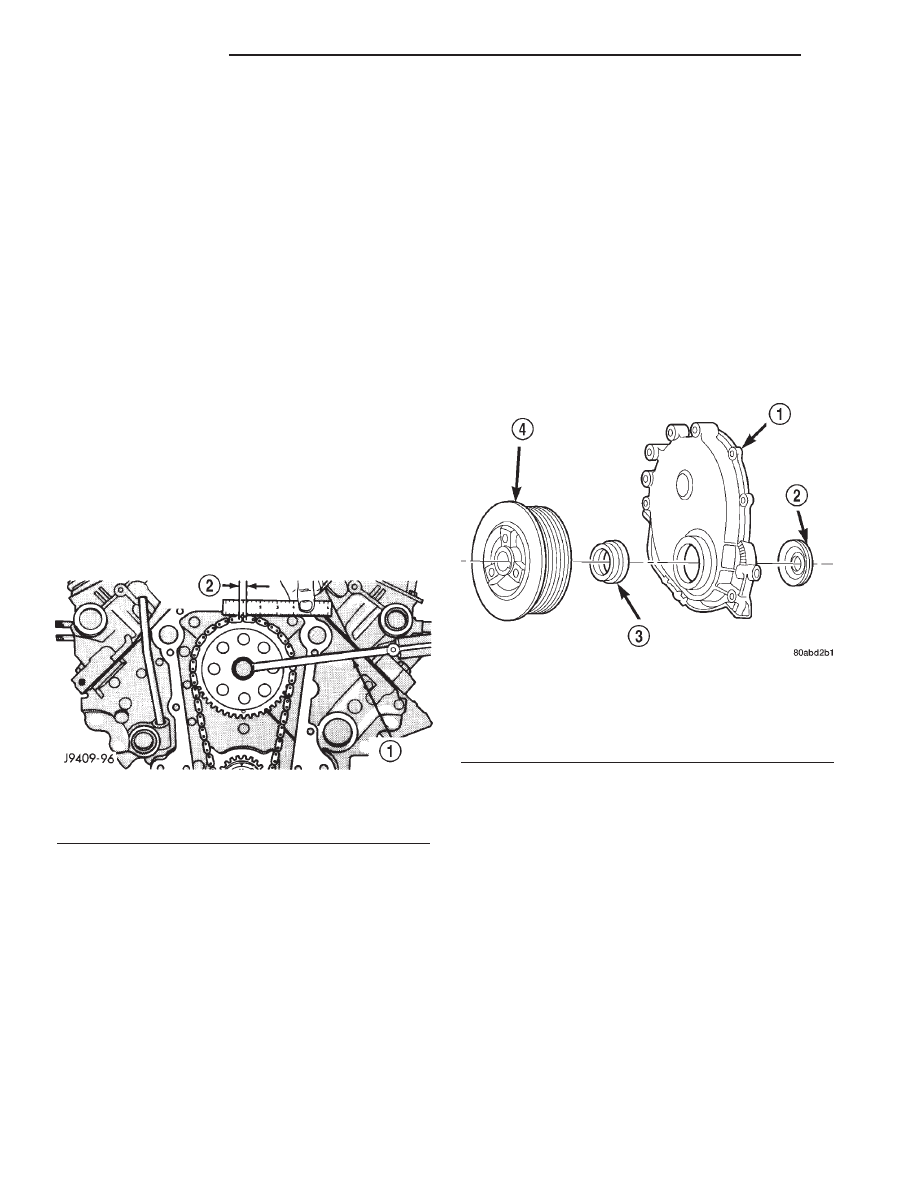
(6) Remove the vibration damper (Refer to 9 -

ENGINE/ENGINE BLOCK/VIBRATION DAMPER -
REMOVAL) (Fig. 80).

(7) Remove the oil pan-to-timing case cover bolts

and timing case cover-to-cylinder block bolts.

(8) Remove the timing case cover and gasket from

the engine.

(9) Pry the crankshaft oil seal from the front of the

timing case cover (Fig. 80).

INSTALLATION

(1) Clean the timing case cover, oil pan and cylin-

der block gasket surfaces.

(2) Install a new crankshaft oil seal in the timing

case cover (Refer to 9 - ENGINE/ENGINE BLOCK/
CRANKSHAFT OIL SEAL - FRONT - INSTALLA-
TION). The open end of the seal should be toward
the inside of the cover. Support the cover at the seal
area while installing the seal. Force it into position
with Seal Installation Tool 6139.

(3) Position the gasket on the cylinder block.
(4) Position the timing case cover on the oil pan

gasket and the cylinder block.

(5) Insert Timing Case Cover Alignment and Seal

Installation Tool 6139 in the crankshaft opening in
the cover (Fig. 81).

(6) Install the timing case cover-to-cylinder block

and the oil pan-to-timing case cover bolts.

Fig. 79 Measuring Timing Chain Wear and Stretch

1 - TORQUE WRENCH
2 - 3.175 MM (0.125 IN.)

Fig. 80 Timing Case Cover Components

1 - TIMING CASE COVER
2 - OIL SLINGER
3 - CRANKSHAFT OIL SEAL
4 - VIBRATION DAMPER PULLEY

9 - 60

ENGINE 2.5L

AN

(7) Tighten the 1/4 inch cover-to-block bolts to 7

N·m (60 in. lbs.) torque. Tighten the 5/16 inch front
cover-to-block bolts to 22 N·m (192 in. lbs.) torque.
Tighten the oil pan-to-cover bolts to 9.5 N·m (84 in.
lbs.) torque.

(8) Remove the cover alignment tool.
(9) Apply a light film of engine oil on the vibration

damper hub contact surface of the seal.

(10) Install the vibration damper (Refer to 9 -

ENGINE/ENGINE BLOCK/VIBRATION DAMPER -
INSTALLATION).

(11) Install the A/C compressor (if equipped) (Refer

to 24 - HEATING & AIR CONDITIONING/PLUMB-
ING/A/C COMPRESSOR - INSTALLATION) and
generator bracket assembly.

(12) Install the engine fan and hub assembly and

shroud.

(13) Install the accessory drive belt (Refer to 7 -

COOLING/ACCESSORY

DRIVE/DRIVE

BELTS

-

INSTALLATION) and tighten to obtain the specified
tension.

(14) Connect negative cable to battery.

TIMING BELT/CHAIN AND
SPROCKETS

REMOVAL

The chain drive system is equipped with a timing

chain tensioner which reduces noise and prolongs
timing chain life. In addition, it compensates for
wear and temperature changes on the valve train for
proper engine operation.

(1) Disconnect negative cable from battery.
(2) Remove the fan and shroud.

(3) Remove the serpentine drive belt (Refer to 7 -

COOLING/ACCESSORY

DRIVE/DRIVE

BELTS

-

REMOVAL).

(4) Remove the crankshaft vibration damper (Refer

to

9

-

ENGINE/ENGINE

BLOCK/VIBRATION

DAMPER - REMOVAL).

(5) Remove the timing case cover (Refer to 9 -

ENGINE/VALVE TIMING/TIMING BELT / CHAIN
COVER(S) - REMOVAL).

(6) Rotate crankshaft until the “0” timing mark is

closest to and on the center line with camshaft
sprocket timing mark (Fig. 82).

(7) Remove the oil slinger from the crankshaft.
(8) Remove

the

camshaft

retaining

bolt

and

remove the sprockets and chain as an assembly (Fig.
83).

Fig. 81 Timing Case Cover Alignment and Seal

Installation Tool 6139

1 - TIMING CASE COVER ALIGNMENT AND SEAL
INSTALLATION TOOL

Fig. 82 Crankshaft—Camshaft Alignment

1 - TIMING MARKS

Fig. 83 Camshaft and Crankshaft Sprockets and

Chain

1 - CAMSHAFT SPROCKET
2 - CRANKSHAFT SPROCKET
3 - CHAIN

AN

ENGINE 2.5L

9 - 61

TIMING BELT / CHAIN COVER(S) (Continued)

INSTALLATION

The chain drive system is equipped with a timing

chain tensioner which reduces noise and prolongs
timing chain life. In addition, it compensates for
wear and temperature changes on the valve train for
proper engine operation.

(1) Turn the tensioner lever to the unlocked (down)

position (Fig. 84).

(2) Pull the tensioner block toward the tensioner

lever to compress the spring. Hold the block and turn
the tensioner lever to the lock position (Fig. 84).

(3) Apply Mopar

t Silicone Rubber Adhesive Seal-

ant to the keyway in the crankshaft and insert the
key. With the key in the crankshaft keyway, install
the crankshaft, camshaft sprockets and timing chain.
Ensure the timing marks on the sprockets are prop-
erly aligned (Fig. 82).

(4) Install the camshaft sprocket retaining bolt

and washer. Tighten the bolt to 108 N·m (80 ft. lbs.)
torque.

(5) To verify correct installation of the timing

chain, turn the crankshaft to position the camshaft

sprocket timing mark as shown in (Fig. 85). Count
the number of chain pins between the timing marks
of both sprockets. There must be 20 pins.

(6) Turn the chain tensioner lever to the unlocked

(down) position (Fig. 84).

(7) Install the oil slinger.
(8) Replace the oil seal in the timing case cover

(Refer to 9 - ENGINE/ENGINE BLOCK/CRANK-
SHAFT OIL SEAL - FRONT - INSTALLATION).

(9) Install the timing case cover and gasket (Refer

to 9 - ENGINE/VALVE TIMING/TIMING BELT /
CHAIN COVER(S) - INSTALLATION).

(10) With the key inserted in the keyway in the

crankshaft, install the vibration damper, washer and
bolt. Lubricate and tighten the bolt to 108 N·m (80 ft.
lbs.) torque.

(11) Install the fan and shroud.
(12) Connect negative cable to battery.

Fig. 84 Loading Timing Chain Tensioner

1 - LOCK
2 - UNLOCK
3 - TENSIONER BLOCK
4 - TENSIONER LEVER

Fig. 85 Verify Sprocket—Chain Installation

1 - CAMSHAFT SPROCKET
2 - 20 PINS
3 - CRANKSHAFT SPROCKET
4 - TIMING MARKS

9 - 62

ENGINE 2.5L

AN

TIMING BELT/CHAIN AND SPROCKETS (Continued)

ENGINE 3.9L

TABLE OF CONTENTS

page

page

ENGINE 3.9L

DESCRIPTION . . . . . . . . . . . . . . . . . . . . . . . . . . . 64
DIAGNOSIS AND TESTING . . . . . . . . . . . . . . . . . 65

ENGINE DIAGNOSIS - INTRODUCTION . . . . . . 65
ENGINE DIAGNOSIS - PERFORMANCE. . . . . . 65
ENGINE DIAGNOSIS - MECHANICAL. . . . . . . . 68
ENGINE DIAGNOSIS - LUBRICATION . . . . . . . 70
CYLINDER COMPRESSION PRESSURE . . . . . 70
CYLINDER COMBUSTION PRESSURE
LEAKAGE. . . . . . . . . . . . . . . . . . . . . . . . . . . . . 71

STANDARD PROCEDURE . . . . . . . . . . . . . . . . . . 71

CYLINDER BORE HONING . . . . . . . . . . . . . . . 71
ENGINE GASKET SURFACE PREPARATION . . 72
ENGINE CORE AND OIL GALLERY PLUGS . . . 72
HYDROSTATIC LOCK. . . . . . . . . . . . . . . . . . . . 73
REPAIR DAMAGED OR WORN THREADS . . . . 73
FORM-IN-PLACE GASKETS AND SEALERS. . . 73

REMOVAL . . . . . . . . . . . . . . . . . . . . . . . . . . . . . . 74
INSTALLATION. . . . . . . . . . . . . . . . . . . . . . . . . . . 75
SPECIFICATIONS . . . . . . . . . . . . . . . . . . . . . . . . 75
SPECIAL TOOLS . . . . . . . . . . . . . . . . . . . . . . . . . 80

AIR CLEANER ELEMENT

REMOVAL . . . . . . . . . . . . . . . . . . . . . . . . . . . . . . 82
INSTALLATION. . . . . . . . . . . . . . . . . . . . . . . . . . . 82

CYLINDER HEAD

DESCRIPTION . . . . . . . . . . . . . . . . . . . . . . . . . . . 82
OPERATION. . . . . . . . . . . . . . . . . . . . . . . . . . . . . 82
DIAGNOSIS AND TESTING . . . . . . . . . . . . . . . . . 82

CYLINDER HEAD GASKET FAILURE . . . . . . . . 82

REMOVAL . . . . . . . . . . . . . . . . . . . . . . . . . . . . . . 83
CLEANING . . . . . . . . . . . . . . . . . . . . . . . . . . . . . . 83
INSPECTION . . . . . . . . . . . . . . . . . . . . . . . . . . . . 84
INSTALLATION. . . . . . . . . . . . . . . . . . . . . . . . . . . 84

CYLINDER HEAD COVER(S)

DESCRIPTION . . . . . . . . . . . . . . . . . . . . . . . . . . . 84
REMOVAL . . . . . . . . . . . . . . . . . . . . . . . . . . . . . . 84
CLEANING . . . . . . . . . . . . . . . . . . . . . . . . . . . . . . 84
INSPECTION . . . . . . . . . . . . . . . . . . . . . . . . . . . . 85
INSTALLATION. . . . . . . . . . . . . . . . . . . . . . . . . . . 85

INTAKE/EXHAUST VALVES & SEATS

DESCRIPTION . . . . . . . . . . . . . . . . . . . . . . . . . . . 85
STANDARD PROCEDURE . . . . . . . . . . . . . . . . . . 85

VALVES, GUIDES AND SPRINGS . . . . . . . . . . . 85

REMOVAL . . . . . . . . . . . . . . . . . . . . . . . . . . . . . . 87
CLEANING . . . . . . . . . . . . . . . . . . . . . . . . . . . . . . 87
INSPECTION . . . . . . . . . . . . . . . . . . . . . . . . . . . . 88
INSTALLATION. . . . . . . . . . . . . . . . . . . . . . . . . . . 88

ENGINE BLOCK

CLEANING . . . . . . . . . . . . . . . . . . . . . . . . . . . . . . 89

INSPECTION . . . . . . . . . . . . . . . . . . . . . . . . . . . . 89

CAMSHAFT & BEARINGS (IN BLOCK)

REMOVAL . . . . . . . . . . . . . . . . . . . . . . . . . . . . . . 89
INSTALLATION. . . . . . . . . . . . . . . . . . . . . . . . . . . 90

CONNECTING ROD BEARINGS

STANDARD PROCEDURE . . . . . . . . . . . . . . . . . . 92

CONNECTING ROD BEARING FITTING . . . . . . 92

CRANKSHAFT

DESCRIPTION . . . . . . . . . . . . . . . . . . . . . . . . . . . 92
OPERATION. . . . . . . . . . . . . . . . . . . . . . . . . . . . . 92
REMOVAL . . . . . . . . . . . . . . . . . . . . . . . . . . . . . . 92
INSTALLATION. . . . . . . . . . . . . . . . . . . . . . . . . . . 92

CRANKSHAFT MAIN BEARINGS

DESCRIPTION . . . . . . . . . . . . . . . . . . . . . . . . . . . 93
OPERATION. . . . . . . . . . . . . . . . . . . . . . . . . . . . . 93
STANDARD PROCEDURE . . . . . . . . . . . . . . . . . . 93

MAIN BEARING FITTING . . . . . . . . . . . . . . . . . 93

REMOVAL . . . . . . . . . . . . . . . . . . . . . . . . . . . . . . 94
INSTALLATION. . . . . . . . . . . . . . . . . . . . . . . . . . . 94

CRANKSHAFT OIL SEAL - FRONT

DESCRIPTION . . . . . . . . . . . . . . . . . . . . . . . . . . . 94
OPERATION. . . . . . . . . . . . . . . . . . . . . . . . . . . . . 94
REMOVAL . . . . . . . . . . . . . . . . . . . . . . . . . . . . . . 94
INSTALLATION. . . . . . . . . . . . . . . . . . . . . . . . . . . 94

CRANKSHAFT OIL SEAL - REAR

DESCRIPTION . . . . . . . . . . . . . . . . . . . . . . . . . . . 95
OPERATION. . . . . . . . . . . . . . . . . . . . . . . . . . . . . 95
DIAGNOSIS AND TESTING . . . . . . . . . . . . . . . . . 95

REAR SEAL AREA LEAKS . . . . . . . . . . . . . . . . 95

REMOVAL . . . . . . . . . . . . . . . . . . . . . . . . . . . . . . 96
INSTALLATION. . . . . . . . . . . . . . . . . . . . . . . . . . . 96

DISTRIBUTOR BUSHING

REMOVAL . . . . . . . . . . . . . . . . . . . . . . . . . . . . . . 98
INSTALLATION. . . . . . . . . . . . . . . . . . . . . . . . . . . 98

HYDRAULIC LIFTERS (CAM IN BLOCK)

DIAGNOSIS AND TESTING . . . . . . . . . . . . . . . . . 99

HYDRAULIC TAPPETS . . . . . . . . . . . . . . . . . . . 99

REMOVAL . . . . . . . . . . . . . . . . . . . . . . . . . . . . . 100
CLEANING . . . . . . . . . . . . . . . . . . . . . . . . . . . . . 100
INSTALLATION . . . . . . . . . . . . . . . . . . . . . . . . . . 100

PISTON & CONNECTING ROD

DESCRIPTION . . . . . . . . . . . . . . . . . . . . . . . . . . 101
STANDARD PROCEDURE . . . . . . . . . . . . . . . . . 101

PISTON FITTING . . . . . . . . . . . . . . . . . . . . . . 101

REMOVAL . . . . . . . . . . . . . . . . . . . . . . . . . . . . . 101
CLEANING . . . . . . . . . . . . . . . . . . . . . . . . . . . . . 102
INSPECTION . . . . . . . . . . . . . . . . . . . . . . . . . . . 102
INSTALLATION . . . . . . . . . . . . . . . . . . . . . . . . . . 102

AN

ENGINE 3.9L

9 - 63


Content   ..  466  467  468  469   ..