Dodge Dakota (R1). Manual - part 467


  Index      Dodge     Dodge Dakota (R1) - service repair manual 2000 year


Search            


Content   ..  465  466  467  468   ..


Dodge Dakota (R1). Manual - part 467


(12) Install the flywheel and torque converter

housing access cover.

(13) Install the engine starter motor.
(14) Connect the exhaust pipe to the hanger and to

the engine exhaust manifold.

(15) Install the oil pan drain plug (Fig. 74).

Tighten the plug to 34 N·m (25 ft. lbs.) torque.

(16) Lower the vehicle.
(17) Connect negative cable to battery.
(18) Fill the oil pan with engine oil to the specified

level.

WARNING: USE EXTREME CAUTION WHEN THE
ENGINE IS OPERATING. DO NOT STAND IN A
DIRECT LINE WITH THE FAN. DO NOT PUT YOUR
HANDS NEAR THE PULLEYS, BELTS OR FAN. DO
NOT WEAR LOOSE CLOTHING.

(19) Start the engine and inspect for leaks.

OIL PRESSURE SENSOR/
SWITCH

DESCRIPTION

The 2–wire, electrical/mechanical engine oil pres-

sure sensor (sending unit) is located in an engine oil
pressure gallery.

OPERATION

The oil pressure sensor uses two circuits. They are:
• A signal to the PCM relating to engine oil pres-

sure

• A sensor ground through the PCM’s sensor

return

The oil pressure sensor returns a voltage signal

back to the PCM relating to engine oil pressure. This
signal is then transferred (bussed) to the instrument
panel on a CCD bus circuit to operate the oil pres-
sure gauge and the check gauges lamp. Ground for
the sensor is provided by the PCM through a low-
noise sensor return.

OIL PUMP

REMOVAL

The positive-displacement gear-type oil pump is

driven by the distributor shaft, which is driven by a
gear on the camshaft. Oil is siphoned into the pump
through an inlet tube and strainer assembly that is
pressed into the pump body.

The pump incorporates a nonadjustable pressure

relief valve to limit maximum pressure to 517 kPa
(75 psi). In the relief position, the valve permits oil to

bypass through a passage in the pump body to the
inlet side of the pump.

Oil pump removal or replacement will not affect

the distributor timing because the distributor drive
gear remains in mesh with the camshaft gear.

(1) Drain the engine oil.
(2) Remove the oil pan (Refer to 9 - ENGINE/LU-

BRICATION/OIL PAN - REMOVAL).

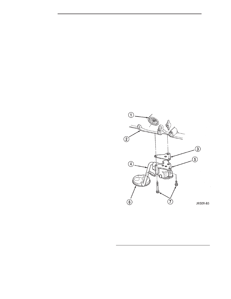
(3) Remove the pump-to-cylinder block attaching

bolts. Remove the pump assembly with gasket (Fig.
75).

CAUTION: If the oil pump is not to be serviced, DO
NOT disturb position of oil inlet tube and strainer
assembly in pump body. If the tube is moved within
the pump body, a replacement tube and strainer
assembly must be installed to assure an airtight
seal.

INSTALLATION

The positive-displacement gear-type oil pump is

driven by the distributor shaft, which is driven by a
gear on the camshaft. Oil is siphoned into the pump
through an inlet tube and strainer assembly that is
pressed into the pump body.

Fig. 75 Oil Pump Assembly

1 - OIL FILTER ADAPTOR
2 - BLOCK
3 - GASKET
4 - OIL INLET TUBE
5 - OIL PUMP
6 - STRAINER ASSEMBLY
7 - ATTACHING BOLTS

9 - 56

ENGINE 2.5L

AN

OIL PAN (Continued)

The pump incorporates a nonadjustable pressure

relief valve to limit maximum pressure to 517 kPa
(75 psi). In the relief position, the valve permits oil to
bypass through a passage in the pump body to the
inlet side of the pump.

Oil pump removal or replacement will not affect

the distributor timing because the distributor drive
gear remains in mesh with the camshaft gear.

(1) Install the oil pump on the cylinder block using

a replacement gasket. Tighten the bolts to 23 N·m
(17 ft. lbs.) torque.

(2) Install the oil pan and gasket (Refer to 9 -

ENGINE/LUBRICATION/OIL

PAN

-

INSTALLA-

TION).

(3) Fill the oil pan with oil to the specified level.

INTAKE MANIFOLD

DESCRIPTION

The aluminum intake manifold is a single plane

design.

The intake manifold and the exhaust manifold

share a common one piece sealing gasket.

DIAGNOSIS AND TESTING - INTAKE
MANIFOLD

An intake manifold air leak is characterized by

lower than normal manifold vacuum. Also, one or
more cylinders may not be functioning.

WARNING: USE EXTREME CAUTION WHEN THE
ENGINE IS OPERATING. DO NOT STAND IN A
DIRECT LINE WITH THE FAN. DO NOT PUT YOUR
HANDS NEAR THE PULLEYS, BELTS OR THE FAN.
DO NOT WEAR LOOSE CLOTHING.

(1) Start the engine.
(2) Spray a small stream of water at the suspected

leak area.

(3) If a change in RPM is observed the area of the

suspected leak has been found.

(4) Repair as required.

REMOVAL

(1) Disconnect the battery negative cable.
(2) Drain the cooling system (Refer to 7 - COOL-

ING - STANDARD PROCEDURE).

(3) Remove the air inlet hose and resonator from

the throttle body and air cleaner (Fig. 76).

(4) Loosen the accessory drive belt tension and

remove the belt from the power steering pump (Refer
to

7

-

COOLING/ACCESSORY

DRIVE/DRIVE

BELTS - REMOVAL).

(5) Remove the power steering pump and brackets

from the water pump and intake manifold. Secure
power steering pump and bracket out of the way.

(6) Perform fuel system pressure release procedure

(Refer to 14 - FUEL SYSTEM/FUEL DELIVERY -
STANDARD PROCEDURE).

(7) Disconnect fuel supply tube from the fuel rail

(Refer to 14 - FUEL SYSTEM/FUEL DELIVERY/
QUICK CONNECT FITTING - STANDARD PROCE-
DURE).

(8) Disconnect the accelerator cable, the cruise

control cable (if equipped), and the transmission line
pressure cable (if equipped) from the throttle body
and remove them from the cable bracket.

CAUTION: When disconnecting the cruise control
connector at the throttle body, DO NOT pry the con-
nector off with pliers or screwdriver. Use finger
pressure only. Prying the connector off could break
it.

(9) Disconnect the electrical connectors. Pull the

harnesses away from the manifold and secure them
so they do not interfere with the manifold removal
and installation process.

• The throttle position sensor.

• The idle air control motor.

• The coolant temperature sensor at the thermo-

stat.

Fig. 76 Air Cleaner, Resonator and Air Inlet Hose

Removal and Installation

1 - AIR CLEANER ASSEMBLY
2 - NUT AND WASHER
3 - RESONATOR ASSEMBLY
4 - AIR INLET HOSE

AN

ENGINE 2.5L

9 - 57

OIL PUMP (Continued)

• The manifold air temperature sensor at the

intake manifold.

• The fuel injectors.

• The oxygen sensor.
(10) Disconnect the crankcase ventilation (CCV)

vacuum hose and manifold absolute pressure (MAP)
sensor vacuum hose connector at the intake mani-
fold.

(11) Disconnect vacuum hose from vacuum port on

the intake manifold.

(12) Disconnect CCV hose at the cylinder head

cover (Fig. 77).

(13) Remove the molded vacuum harness.
(14) Disconnect the vacuum brake booster hose at

the intake manifold.

(15) Remove bolts 2 through 5 securing the intake

manifold to the cylinder head (Fig. 78). Slightly
loosen bolt No.1 and nuts 6 and 7.

(16) Remove the intake manifold and gaskets.

Drain the coolant from the manifold.

CLEANING

CAUTION: DO NOT allow foreign material to enter
either the intake manifold ports, or the cylinder
head ports.

Clean the intake manifold to cylinder head mating

surfaces.

INSPECTION

Inspect manifold to cylinder head mating surfaces

for cracks and/or pitting. Inspect manifold for warp
or twist.

INSTALLATION

(1) Clean the intake manifold and cylinder head

mating surfaces. DO NOT allow foreign material
to enter either the intake manifold or the ports
in the cylinder head.

(2) Install the new intake manifold gasket over the

locating dowels.

(3) Position the manifold in place and finger

tighten the mounting bolts.

(4) Tighten the fasteners in sequence and to the

specified torque (Fig. 78).

• Fastener No.1—Tighten to 41 N·m (30 ft. lbs.)

torque.

• Fasteners Nos.2 through 5—Tighten to 31 N·m

(23 ft. lbs.) torque.

• Fasteners Nos.6 and 7—Tighten to 23 N·m (17

ft. lbs.) torque.

(5) Connect fuel supply tube to the fuel rail inlet

(Refer to 14 - FUEL SYSTEM/FUEL DELIVERY/
QUICK CONNECT FITTING - STANDARD PROCE-
DURE).

(6) Pull out on the fuel supply tube to ensure that

it is locked in place.

(7) Connect the molded vacuum hoses to the vac-

uum port on the intake manifold and the cylinder
head cover.

(8) Connect the electrical connectors.
• The throttle position sensor.

• The idle air control motor.

• The coolant temperature sensor at the thermo-

stat housing.

• The fuel injectors.

• The air manifold temperature sensor.

• The oxygen sensor.
(9) Connect the CCV vacuum hose and MAP sen-

sor vacuum hose connectors to the throttle body.

(10) Install the power steering pump and bracket

assembly to the water pump and intake manifold.
Hand start the three (3) tensioner bracket to p/s
pump to intake manifold bolts and the two (2) ten-
sioner bracket to water pump bolts.

(11) Tighten the power steering pump bolts to 28

N·m (21 ft. lbs.) Tighten the tensioner bracket to
water pump bolts to 28 N·m (21 ft. lbs.).

(12) Connect the accelerator cable, cruise control

cable (if equipped), and the transmission line pres-
sure cable (if equipped) to the hold-down bracket and
the throttle lever.

(13) Install and tension the accessory drive belt.

(Refer to 7 - COOLING/ACCESSORY DRIVE/DRIVE
BELTS - INSTALLATION).

Fig. 77 Crankcase Ventilation (CCV) Hose—2.5L

1 - AIR INLET FITTING
2 - AIR FILTER COVER
3 - FIXED ORIFICE FITTING

9 - 58

ENGINE 2.5L

AN

INTAKE MANIFOLD (Continued)

CAUTION: Ensure that the accessory drive belt is
routed correctly. Failure to do so can cause the
water pump to turn in the opposite direction result-
ing in engine overheating. Refer to Group 7, Cool-
ing System for the proper procedure.

(14) Connect the air inlet hose and resonator to

the throttle body and the air cleaner. Tighten clamps
to 4 N·m (35 in. lbs.).

(15) Connect the battery negative cable.
(16) Start the engine and check for leaks.

EXHAUST MANIFOLD

DESCRIPTION

The exhaust manifold is constructed of cast iron

and has a ball flange designed exhaust pipe mount-
ing flange.

The exhaust manifold and the intake manifold

share a common one piece sealing gasket.

OPERATION

The exhaust manifold collects the engine exhaust

exiting the combustion chambers, then channels the
exhaust gases to the exhaust pipe attached to the
manifold.

REMOVAL

(1) Disconnect the battery negative cable.
(2) Drain the cooling system (Refer to 7 - COOL-

ING - STANDARD PROCEDURE).

(3) Raise the vehicle.
(4) Disconnect the exhaust pipe from the engine

exhaust manifold.

(5) Lower the vehicle.
(6) Remove intake manifold (Refer to 9 - ENGINE/

MANIFOLDS/INTAKE MANIFOLD - REMOVAL).

(7) Remove fasteners 2 through 5 and remove the

intake manifold (Fig. 78).

(8) Remove fasteners 1, 6 and 7 and remove the

engine exhaust manifold (Fig. 78).

CLEANING

Clean mating surfaces on cylinder head and mani-

fold, wash with solvent and blow dry with com-
pressed air.

INSPECTION

Inspect manifold for cracks, Inspect mating sur-

faces of manifold for flatness with a straight edge.
Seal surfaces must be flat within 0.1 mm (0.004 inch)
overall.

INSTALLATION

(1) Clean the intake and engine exhaust manifolds

and cylinder head mating surfaces. DO NOT allow
foreign material to enter either the intake man-
ifold or the ports in the cylinder head.

(2) Install a new intake manifold gasket over the

alignment dowels on the cylinder head.

(3) Install the engine exhaust manifold assembly.

Exhaust manifold must be centrally located
over the end studs and spacer (Fig. 78).

(4) Tighten bolt No.1 to 41 N·m (30 ft. lbs.) torque

(Fig. 78).

(5) Install the intake manifold on the cylinder

head dowels (Fig. 78).

(6) Install bolts 2 through 5 (Fig. 78). Tighten

these bolts to 31 N·m (23 ft. lbs.) torque.

(7) Install new engine exhaust manifold spacers

over the engine exhaust manifold mounting studs in
the cylinder head (Fig. 78).

(8) Tighten nuts 6 and 7 to 23 N·m (17 ft. lbs.)

torque (Fig. 78).

(9) Install the intake manifold (Refer to 9 -

ENGINE/MANIFOLDS/INTAKE

MANIFOLD

-

INSTALLATION).

(10) Raise the vehicle.
(11) Connect the exhaust pipe to the engine

exhaust manifold. Tighten the bolts to 31 N·m (23 ft.
lbs.) torque.

(12) Lower the vehicle.
(13) Refill cooling system (Refer to 7 - COOLING -

STANDARD PROCEDURE).

(14) Connect the battery negative cable.
(15) Start the engine and check for leaks.

Fig. 78 Intake/Exhaust Manifold Removal/Installation

AN

ENGINE 2.5L

9 - 59

INTAKE MANIFOLD (Continued)


Content   ..  465  466  467  468   ..