Dodge Dakota (R1). Manual - part 296


  Index      Dodge     Dodge Dakota (R1) - service repair manual 2000 year


Search            


Content   ..  294  295  296  297   ..


Dodge Dakota (R1). Manual - part 296


(4) Clean the battery thermal guard with a sodium

bicarbonate (baking soda) and warm water cleaning
solution using a stiff bristle parts cleaning brush to
remove any acid film.

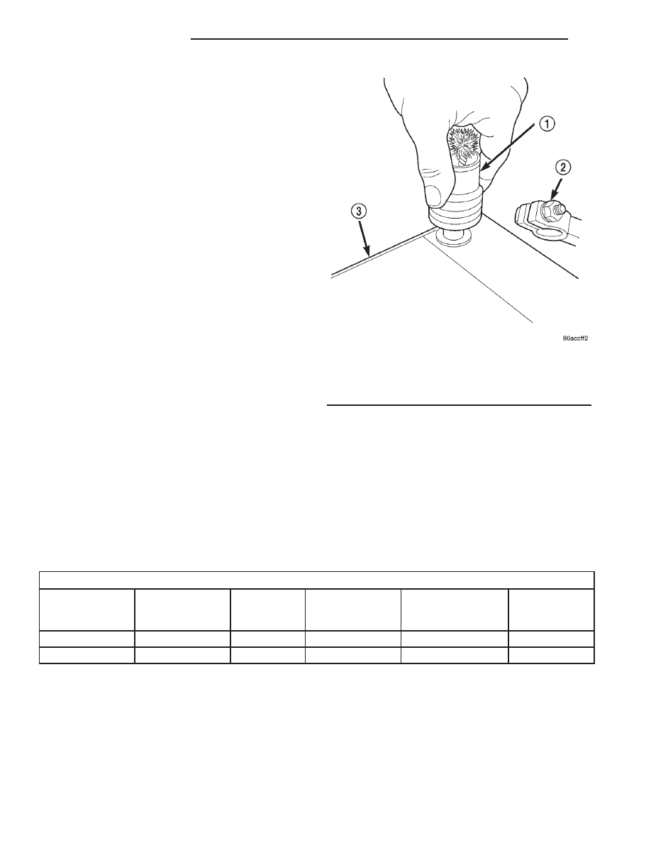
(5) Clean any corrosion from the battery terminal

posts with a wire brush or a post and terminal
cleaner, and a sodium bicarbonate (baking soda) and
warm water cleaning solution (Fig. 3).

INSPECTION

The following information details the recommended

inspection procedures for the battery and related
components. In addition to the maintenance sched-
ules found in this service manual and the owner’s
manual, it is recommended that these procedures be
performed any time the battery or related compo-
nents must be removed for vehicle service.

(1) Inspect the battery cable terminal clamps for

damage. Replace any battery cable that has a dam-
aged or deformed terminal clamp.

(2) Inspect the battery tray and battery holddown

hardware for damage. Replace any damaged parts.

(3) Slide the thermal guard off of the battery case,

if equipped. Inspect the battery case for cracks or
other damage that could result in electrolyte leaks.
Also, check the battery terminal posts for looseness.
Batteries with damaged cases or loose terminal posts
must be replaced.

(4) Inspect the battery thermal guard for tears,

cracks, deformation or other damage. Replace any
battery thermal guard that has been damaged.

(5) Inspect the battery built-in test indicator sight

glass for an indication of the battery condition. If the

battery is discharged, charge as required. Refer to
Standard Procedures for the proper battery built-in
indicator test procedures. Also refer to Standard Pro-
cedures for the proper battery charging procedures.

SPECIFICATIONS

BATTERY

Battery Classifications and Ratings

Part Number

BCI Group Size

Classification

Cold

Cranking

Amperage

Reserve

Capacity

Ampere-Hours

Load Test

Amperage

56027100

27

600

120 Minutes

66

300

56027302

27

750

150 Minutes

75

375

BATTERY

DESCRIPTION

A large capacity, low-maintenance storage battery

(Fig. 4) is standard factory-installed equipment on
this model. Refer to Battery Specifications for the
proper specifications of the factory-installed batteries
available on this model. Male post type terminals

made of a soft lead material protrude from the top of
the molded plastic battery case to provide the means
for connecting the battery to the vehicle electrical
system. The battery positive terminal post is physi-
cally larger in diameter than the negative terminal
post to ensure proper battery connection. The letters
POS and NEG are also molded into the top of the
battery case adjacent to their respective positive and
negative terminal posts for identification confirma-

Fig. 3 Clean Battery Terminal Post - Typical

1 - TERMINAL BRUSH
2 - BATTERY CABLE
3 - BATTERY

8F - 6

BATTERY SYSTEM

AN

BATTERY SYSTEM (Continued)

tion. Refer to Battery Cables for more information on
the battery cables that connect the battery to the
vehicle electrical system.

The battery is made up of six individual cells that

are connected in series. Each cell contains positively
charged plate groups that are connected with lead
straps to the positive terminal post, and negatively
charged plate groups that are connected with lead
straps to the negative terminal post. Each plate con-
sists of a stiff mesh framework or grid coated with
lead dioxide (positive plate) or sponge lead (negative
plate). Insulators or plate separators made of a non-
conductive material are inserted between the positive
and negative plates to prevent them from contacting
or shorting against one another. These dissimilar
metal plates are submerged in a sulfuric acid and
water solution called an electrolyte.

The factory-installed battery has a built-in test

indicator (hydrometer). The color visible in the sight
glass of the indicator will reveal the battery condi-
tion. Refer to Standard Procedures for the proper
built-in indicator test procedures. The factory-in-
stalled low-maintenance battery has non-re-
movable battery cell caps. 
Water cannot be added
to this battery. The battery is not sealed and has
vent holes in the cell caps. The chemical composition
of the metal coated plates within the low-mainte-
nance battery reduces battery gassing and water

loss, at normal charge and discharge rates. There-
fore, the battery should not require additional water
in normal service. Rapid loss of electrolyte can be
caused by an overcharging condition. Be certain to
diagnose the charging system before returning the
vehicle to service. Refer to Charging System for the
proper charging system diagnosis and testing proce-
dures.

OPERATION

The battery is designed to store electrical energy in

a chemical form. When an electrical load is applied to
the terminals of the battery, an electrochemical reac-
tion occurs. This reaction causes the battery to dis-
charge electrical current from its terminals. As the
battery discharges, a gradual chemical change takes
place within each cell. The sulfuric acid in the elec-
trolyte combines with the plate materials, causing
both plates to slowly change to lead sulfate. At the
same time, oxygen from the positive plate material
combines with hydrogen from the sulfuric acid, caus-
ing the electrolyte to become mainly water. The
chemical changes within the battery are caused by
the movement of excess or free electrons between the
positive and negative plate groups. This movement of
electrons

produces

a

flow

of

electrical

current

through the load device attached to the battery ter-
minals.

As the plate materials become more similar chem-

ically, and the electrolyte becomes less acid, the volt-
age potential of each cell is reduced. However, by
charging the battery with a voltage higher than that
of the battery itself, the battery discharging process
is reversed. Charging the battery gradually changes
the sulfated lead plates back into sponge lead and
lead dioxide, and the water back into sulfuric acid.
This action restores the difference in the electron
charges deposited on the plates, and the voltage
potential of the battery cells. For a battery to remain
useful, it must be able to produce high-amperage cur-
rent over an extended period. A battery must also be
able to accept a charge, so that its voltage potential
may be restored.

The battery is vented to release excess hydrogen

gas that is created when the battery is being charged
or discharged. However, even with these vents,
hydrogen gas can collect in or around the battery. If
hydrogen gas is exposed to flame or sparks, it may
ignite. If the electrolyte level is low, the battery may
arc internally and explode. If the battery is equipped
with removable cell caps, add distilled water when-
ever the electrolyte level is below the top of the
plates. If the battery cell caps cannot be removed, the
battery must be replaced if the electrolyte level
becomes low.

Fig. 4 Low-Maintenance Battery - Typical

1 - POSITIVE POST
2 - VENT
3 - CELL CAP
4 - TEST INDICATOR
5 - CELL CAP
6 - VENT
7 - NEGATIVE POST
8 - GREEN BALL
9 - ELECTROLYTE LEVEL
10 - PLATE GROUPS
11 - LOW-MAINTENANCE BATTERY

AN

BATTERY SYSTEM

8F - 7

BATTERY (Continued)

DIAGNOSIS AND TESTING - BATTERY

The battery must be completely charged and the

top, posts and terminal clamps should be properly
cleaned and inspected before diagnostic procedures
are performed. Refer to Battery System Cleaning for
the proper cleaning procedures, and Battery System
Inspection for the proper battery inspection proce-
dures. Refer to Standard Procedures for the proper
battery charging procedures.

WARNING: IF THE BATTERY SHOWS SIGNS OF
FREEZING, LEAKING OR LOOSE POSTS, DO NOT
TEST, ASSIST-BOOST, OR CHARGE. THE BATTERY
MAY ARC INTERNALLY AND EXPLODE. PERSONAL
INJURY AND/OR VEHICLE DAMAGE MAY RESULT.

WARNING: EXPLOSIVE HYDROGEN GAS FORMS IN
AND AROUND THE BATTERY. DO NOT SMOKE,
USE FLAME, OR CREATE SPARKS NEAR THE BAT-
TERY. PERSONAL INJURY AND/OR VEHICLE DAM-
AGE MAY RESULT.

WARNING: THE BATTERY CONTAINS SULFURIC
ACID, WHICH IS POISONOUS AND CAUSTIC. AVOID
CONTACT WITH THE SKIN, EYES, OR CLOTHING.
IN THE EVENT OF CONTACT, FLUSH WITH WATER
AND CALL A PHYSICIAN IMMEDIATELY. KEEP OUT
OF THE REACH OF CHILDREN.

WARNING: IF THE BATTERY IS EQUIPPED WITH
REMOVABLE CELL CAPS, BE CERTAIN THAT EACH
OF THE CELL CAPS ARE IN PLACE AND TIGHT
BEFORE THE BATTERY IS RETURNED TO SER-
VICE. PERSONAL INJURY AND/OR VEHICLE DAM-
AGE MAY RESULT FROM LOOSE OR MISSING
CELL CAPS.

The condition of a battery is determined by two cri-

teria:

• State-Of-Charge - This can be determined by

checking the specific gravity of the battery electrolyte
(built-in indicator test or hydrometer test), or by
checking the battery voltage (open-circuit voltage
test).

• Cranking Capacity - This can be determined

by performing a battery load test, which measures
the ability of the battery to supply high-amperage
current.

First, determine the battery state-of-charge. This

can be done in one of three ways. If the battery has a
built-in test indicator, perform the built-in indicator
test to determine the state-of-charge. If the battery
has no built-in test indicator but does have remov-
able cell caps, perform the hydrometer test to deter-

mine the state-of-charge. If the battery cell caps are
not removable, or a hydrometer is not available, per-
form the open-circuit voltage test to determine the
state-of-charge. Refer to open-circuit voltage test in
the Standard Procedures section of this group.

Second, determine the battery cranking capacity by

performing a load test. The battery must be charged
before proceeding with a load test if:

• The battery built-in test indicator has a black or

dark color visible.

• The temperature corrected specific gravity of the

battery electrolyte is less than 1.235.

• The battery open-circuit voltage is less than 12.4

volts.

A battery that will not accept a charge is faulty,

and

must

be

replaced.

Further

testing

is

not

required. A fully-charged battery must be load tested
to determine its cranking capacity. A battery that is
fully-charged, but does not pass the load test, is
faulty and must be replaced.

NOTE: Completely discharged batteries may take
several hours to accept a charge. Refer to Standard
Procedures for the proper battery charging proce-
dures.

A battery is fully-charged when:
• All battery cells are gassing freely during charg-

ing.

• A green color is visible in the sight glass of the

battery built-in test indicator.

• Three corrected specific gravity tests, taken at

one-hour intervals, indicate no increase in the spe-
cific gravity of the battery electrolyte.

• Open-circuit voltage of the battery is 12.4 volts

or greater.

STANDARD PROCEDURE - CHECKING BATTERY
ELECTROLYTE LEVEL

The following procedure can be used to check the

electrolyte level in the battery.

(1) Remove the battery caps (Fig. 5).
(2) Look through the battery cap holes to deter-

mine the level of the electrolyte in the battery (Fig.
6). The electrolyte should be approximately 1 centi-
meter above the battery plates or until the hook
inside the battery cap holes is covered.

(3) Add only distilled water until the electrolyte

level is approx. one centimeter above the plates.

8F - 8

BATTERY SYSTEM

AN

BATTERY (Continued)

STANDARD PROCEDURE - BATTERY
CHARGING

Battery charging is the means by which the bat-

tery can be restored to its full voltage potential. A
battery is fully-charged when:

• All of the battery cells are gassing freely during

battery charging.

• A green color is visible in the sight glass of the

battery built-in test indicator.

• Three hydrometer tests, taken at one-hour inter-

vals, indicate no increase in the temperature-cor-
rected specific gravity of the battery electrolyte.

• Open-circuit voltage of the battery is 12.65 volts

or above.

WARNING: NEVER EXCEED TWENTY AMPERES
WHEN CHARGING A COLD (-1° C [30° F] OR
LOWER) BATTERY. THE BATTERY MAY ARC INTER-
NALLY AND EXPLODE. PERSONAL INJURY AND/OR
VEHICLE DAMAGE MAY RESULT.

WARNING: IF THE BATTERY SHOWS SIGNS OF
FREEZING, LEAKING OR LOOSE POSTS, DO NOT
TEST, ASSIST-BOOST, OR CHARGE. THE BATTERY
MAY ARC INTERNALLY AND EXPLODE. PERSONAL
INJURY AND/OR VEHICLE DAMAGE MAY RESULT.

WARNING: EXPLOSIVE HYDROGEN GAS FORMS IN
AND AROUND THE BATTERY. DO NOT SMOKE,
USE FLAME, OR CREATE SPARKS NEAR THE BAT-
TERY. PERSONAL INJURY AND/OR VEHICLE DAM-
AGE MAY RESULT.

WARNING: THE BATTERY CONTAINS SULFURIC
ACID, WHICH IS POISONOUS AND CAUSTIC. AVOID
CONTACT WITH THE SKIN, EYES, OR CLOTHING.
IN THE EVENT OF CONTACT, FLUSH WITH WATER
AND CALL A PHYSICIAN IMMEDIATELY. KEEP OUT
OF THE REACH OF CHILDREN.

WARNING: IF THE BATTERY IS EQUIPPED WITH
REMOVABLE CELL CAPS, BE CERTAIN THAT EACH
OF THE CELL CAPS IS IN PLACE AND TIGHT
BEFORE THE BATTERY IS RETURNED TO SER-
VICE. PERSONAL INJURY AND/OR VEHICLE DAM-
AGE MAY RESULT FROM LOOSE OR MISSING
CELL CAPS.

CAUTION: Always disconnect and isolate the bat-
tery negative cable before charging a battery. Do
not exceed sixteen volts while charging a battery.
Damage to the vehicle electrical system compo-
nents may result.

Fig. 5 Battery Caps - Export Battery

1 - BATTERY CAP
2 - BATTERY

Fig. 6 Hook Inside Battery Cap Holes - Export

Battery

1 - BATTERY SURFACE COVER
2 - HOOK

AN

BATTERY SYSTEM

8F - 9

BATTERY (Continued)


Content   ..  294  295  296  297   ..