Dodge Dakota (R1). Manual - part 274


  Index      Dodge     Dodge Dakota (R1) - service repair manual 2000 year


Search            


Content   ..  272  273  274  275   ..


Dodge Dakota (R1). Manual - part 274


STANDARD PROCEDURE - ROUTINE LEVEL
CHECK

NOTE: Do not remove radiator cap for routine cool-
ant level inspections. The coolant level can be
checked at coolant recovery bottle (Fig. 9).

The coolant reserve/overflow system provides a

quick method for determining coolant level without
removing radiator pressure cap. With engine not run-
ning, open the coolant recovery bottle cap and
remove coolant level indicator dipstick to observe
coolant level in coolant recovery bottle. The coolant
level should be between ADD and FULL marks. If
the coolant level is at or below the ADD mark, fill
the recovery bottle with a 50/50 mixture of antifreeze
and water ONE QUART AT A TIME. Repeat this pro-
cedure until the coolant level is at the FULL mark.

COOLANT SELECTION AND
ADDITIVES

DESCRIPTION

The presence of aluminum components in the cool-

ing system requires strict corrosion protection. Main-
tain coolant at specified level with a mixture of
ethylene-glycol

based

antifreeze

and

water.

DaimlerChrysler

Corporation

recommends

Mopar

Antifreeze or equivalent. If coolant becomes contami-

nated or looses color, drain and flush cooling system
and fill with correctly mixed solution.

CAUTION: Do not use coolant additives that are
claimed to improve engine cooling.

ELECTRIC COOLING FAN

DIAGNOSIS AND TESTING - ELECTRIC
COOLING FAN

The powertrain control module (PCM) will set a

diagnostic trouble code (DTC) in memory if it detects
a problem in the electric cooling fan relay or circuit
(Refer to 25 - EMISSIONS CONTROL - DESCRIP-
TION).

The DTC can also be accessed through the DRB

scan tool. Refer to the appropriate Powertrain Diag-
nostic Procedures manual for diagnostic information
and operation of the DRB scan tool (Fig. 10).

RADIATOR FAN MOTOR INOPERATIVE

Equipment Required:

• DRB Scan Tool

• Volt/Ohm meter

• Wiring Diagrams section of this manual

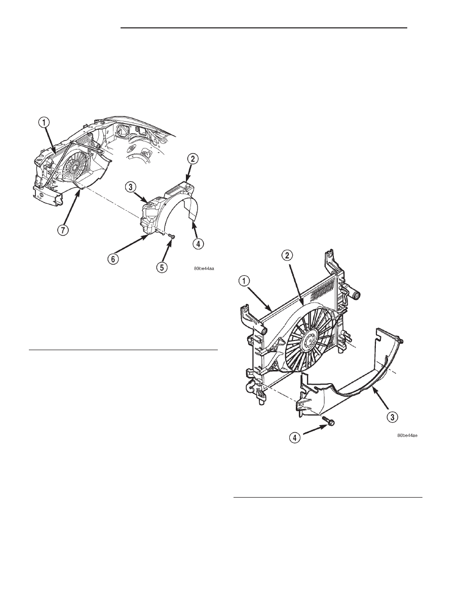
Fig. 9 Coolant Recovery Bottle Location

1 - RADIATOR
2 - WASHER FLUID RESERVOIR
3 - COOLANT OVERFLOW/RESERVOIR
4 - FAN SHROUD (UPPER)
5 - SCREW
6 - INTERLOCKING PINS
7 - FAN SHROUD (LOWER)

Fig. 10 Electrical Cooling Fan

1 - RADIATOR
2 - ELECTRIC FAN ASSEMBLY
3 - FAN SHROUD (LOWER)
4 - SCREW

7a - 42

5.2L ENGINE

R1

COOLANT (Continued)

Test Procedure:

(1) Inspect 10A fuse in junction block and 40A

maxi fuse in PDC (Fig. 11).

(2) Remove Cooling Fan Relay from the PDC and

make the following checks at the relay connector:

• Apply 12 volts (using a fused 14-gauge wire) to

circuit C25 (relay terminal 87). If fan does not come
on, check for open in circuit C25 or Z1. If circuits are
o.k., replace the cooling fan motor.

• With the ignition key “off” check for battery volt-

age at circuit C28 (relay terminal 30). If no battery
voltage present check for open/shorted circuit C28
between the PDC and relay.

• With the ignition key in the “run” position check

for battery voltage at circuit F18 (relay terminal 86).
If no battery voltage present, check for open/short in
circuit F18 between the junction block and the relay.

• If no problems are detected, install the DRB

(refer to the appropriate Powertrain Diagnostic Pro-
cedures manual for DRB scan tool operating instruc-
tions) and start the engine. Clip a 12V test light to
the battery positive terminal and probe circuit C27
(relay terminal 85). When the engine temperature
reaches 110° C (230° F), or A/C is requested, the test
light should light. If not, check circuit C27 for open.

• If no problems are detected at this point, replace

the cooling fan relay.

FAN BLADE

CLEANING

Clean the fan blades using a mild soap and water.

Do not use an abrasive to clean the blades.

INSPECTION

WARNING:

DO

NOT

ATTEMPT

TO

BEND

OR

STRAIGHTEN FAN BLADES IF FAN IS NOT WITHIN
SPECIFICATIONS.

CAUTION:

If

fan

blade

assembly

is

replaced

because of mechanical damage, water pump and
viscous fan drive should also be inspected. These
components could have been damaged due to
excessive vibration.

(1) Remove fan blade assembly from viscous fan

drive unit (four bolts).

(2) Lay fan on a flat surface with leading edge fac-

ing down. With tip of blade touching flat surface,
replace fan if clearance between opposite blade and
surface is greater than 2.0 mm (.090 inch). Rocking
motion of opposite blades should not exceed 2.0 mm
(.090 inch). Test all blades in this manner.

(3) Inspect fan assembly for cracks, bends, loose

rivets or broken welds. Replace fan if any damage is
found.

HOSE CLAMPS

DESCRIPTION

The cooling system utilizes both worm drive and

spring type hose clamps. If a spring type clamp
replacement is necessary, replace with the original
Mopar

t equipment spring type clamp.

CAUTION: A number or letter is stamped into the
tongue of constant tension clamps. If replacement
is necessary, use only a original equipment clamp
with matching number or letter (Fig. 12).

OPERATION

The worm type hose clamp uses a specified torque

value to maintain proper tension on a hose connec-
tion.

The spring type hose clamp applies constant ten-

sion on a hose connection. To remove a spring type
hose clamp, only use constant tension clamp pliers
designed to compress the hose clamp.

Fig. 11 Power Distribution Center (PDC)

1 - POWER DISTRIBUTION CENTER (PDC)

R1

5.2L ENGINE

7a - 43

ELECTRIC COOLING FAN (Continued)

THERMOSTAT

DESCRIPTION

CAUTION: Do not operate an engine without a ther-
mostat, except for servicing or testing.

The thermostat on all gas powered engines is

located beneath the thermostat housing at the front
of the intake manifold (Fig. 13).

The thermostat is a wax pellet driven, reverse pop-

pet choke type.

Coolant leakage into the pellet container will cause

the thermostat to fail in the open position. Thermo-
stats very rarely stick. Do not attempt to free a ther-
mostat with a prying device.

The same thermostat is used for winter and sum-

mer seasons. An engine should not be operated with-
out a thermostat, except for servicing or testing.
Operating without a thermostat causes longer engine
warmup

time,

unreliable

warmup

performance,

increased exhaust emissions and crankcase condensa-
tion that can result in sludge formation.

OPERATION

The wax pellet is located in a sealed container at

the spring end of the thermostat. When heated, the
pellet expands, overcoming closing spring tension
and water pump pressure to force the valve to open.

DIAGNOSIS AND TESTING - GAS ENGINE

ON-BOARD DIAGNOSTICS

All gasoline powered models are equipped with

On-Board Diagnostics for certain cooling system com-
ponents (Refer to 7 - COOLING/ENGINE - DIAGNO-
SIS AND TESTING). If the powertrain control
module (PCM) detects low engine coolant tempera-
ture, it will record a Diagnostic Trouble Code (DTC)
in the PCM memory. Do not change a thermostat for
lack of heat as indicated by the instrument panel
gauge or by poor heater performance unless a DTC is
present. Refer to the Diagnosis section of this group
for other probable causes. For other DTC numbers
(Refer to 25 - EMISSIONS CONTROL - DESCRIP-
TION).

The DTC can also be accessed through the DRB

scan tool. Refer to the appropriate Powertrain Diag-
nostic Procedures manual for diagnostic information
and operation of the DRB scan tool.

REMOVAL

WARNING: DO NOT LOOSEN RADIATOR DRAIN-
COCK WITH SYSTEM HOT AND PRESSURIZED.
SERIOUS BURNS FROM COOLANT CAN OCCUR.

Fig. 12 Spring Clamp Size Location

1 - SPRING CLAMP SIZE LOCATION

Fig. 13 Thermostat—Typical

1 - THERMOSTAT HOUSING
2 - GASKET
3 - INTAKE MANIFOLD
4 - THERMOSTAT
5 - MACHINED GROOVE

7a - 44

5.2L ENGINE

R1

HOSE CLAMPS (Continued)

Do not waste reusable coolant. If solution is clean,

drain coolant into a clean container for reuse.

If thermostat is being replaced, be sure that

replacement is specified thermostat for vehicle model
and engine type.

Factory installed thermostat housings on 5.2L/5.9L

engines are installed on a gasket with an anti-stick
coating. This will aid in gasket removal and clean-up.

(1) Disconnect negative battery cable at battery.
(2) Drain cooling system until coolant level is

below thermostat (Refer to 7 - COOLING/ENGINE -
STANDARD PROCEDURE).

(3) Air

Conditioned

vehicles:

Remove

support

bracket (generator mounting bracket-to-intake mani-
fold) located near rear of generator (Fig. 14).

(4) On air conditioning equipped vehicles, the gen-

erator must be partially removed.

(a) Remove generator drive belt as follows: Drive

belts on 5.2L/5.9L engines are equipped with a
spring loaded automatic belt tensioner (Fig. 15).

(b) Attach a socket/wrench to pulley mounting

bolt of automatic tensioner (Fig. 15).

(c) Rotate

tensioner

assembly

clockwise

(as

viewed from front) until tension has been relieved
from belt.

(d) Remove belt from vehicle.
(e) Remove two generator mounting bolts. Do

not remove any wiring at generator. If equipped
with 4WD, unplug 4WD indicator lamp wiring har-
ness (located near rear of generator).

(f) Remove generator. Position generator to gain

access for thermostat gasket removal.

WARNING: CONSTANT TENSION HOSE CLAMPS
ARE USED ON MOST COOLING SYSTEM HOSES.
WHEN REMOVING OR INSTALLING, USE ONLY

TOOLS DESIGNED FOR SERVICING THIS TYPE OF
CLAMP, SUCH AS SPECIAL CLAMP TOOL (NUMBER
6094) (Fig. 41). SNAP-ON CLAMP TOOL (NUMBER
HPC-20) MAY BE USED FOR LARGER CLAMPS.
ALWAYS WEAR SAFETY GLASSES WHEN SERVIC-
ING CONSTANT TENSION CLAMPS.

CAUTION: A number or letter is stamped into the
tongue of constant tension clamps (Fig. 42). If
replacement is necessary, use only an original
equipment clamp with matching number or letter.

(5) Remove upper radiator hose clamp and upper

radiator hose at thermostat housing.

(6) Position wiring harness (behind thermostat

housing) to gain access to thermostat housing.

(7) Remove thermostat housing mounting bolts,

thermostat housing, gasket and thermostat (Fig. 16).
Discard old gasket.

INSTALLATION

(1) Clean mating areas of intake manifold and

thermostat housing.

(2) Install thermostat (spring side down) into

recessed machined groove on intake manifold (Fig.
16).

(3) Install gasket on intake manifold and over

thermostat (Fig. 16).

Fig. 14 Generator Support Bracket—5.2L/5.9L

Engine

1 - IDLER PULLEY BUSHING
2 - A/C AND/OR GENERATOR MOUNTING BRACKET
3 - IDLER PULLEY
4 - SCREW AND WASHER

Fig. 15 Automatic Belt Tensioner—5.2L/5.9L Engines

1 - IDLER PULLEY
2 - TENSIONER
3 - FAN BLADE

R1

5.2L ENGINE

7a - 45

THERMOSTAT (Continued)


Content   ..  272  273  274  275   ..