Dodge Dakota (R1). Manual - part 206


  Index      Dodge     Dodge Dakota (R1) - service repair manual 2000 year


Search            


Content   ..  204  205  206  207   ..


Dodge Dakota (R1). Manual - part 206


PINION GEAR/RING GEAR/
TONE RING

REMOVAL

NOTE: The ring gear and pinion are serviced in a
matched set. Never replace one without replacing
the other.

(1) Remove differential from axle housing.
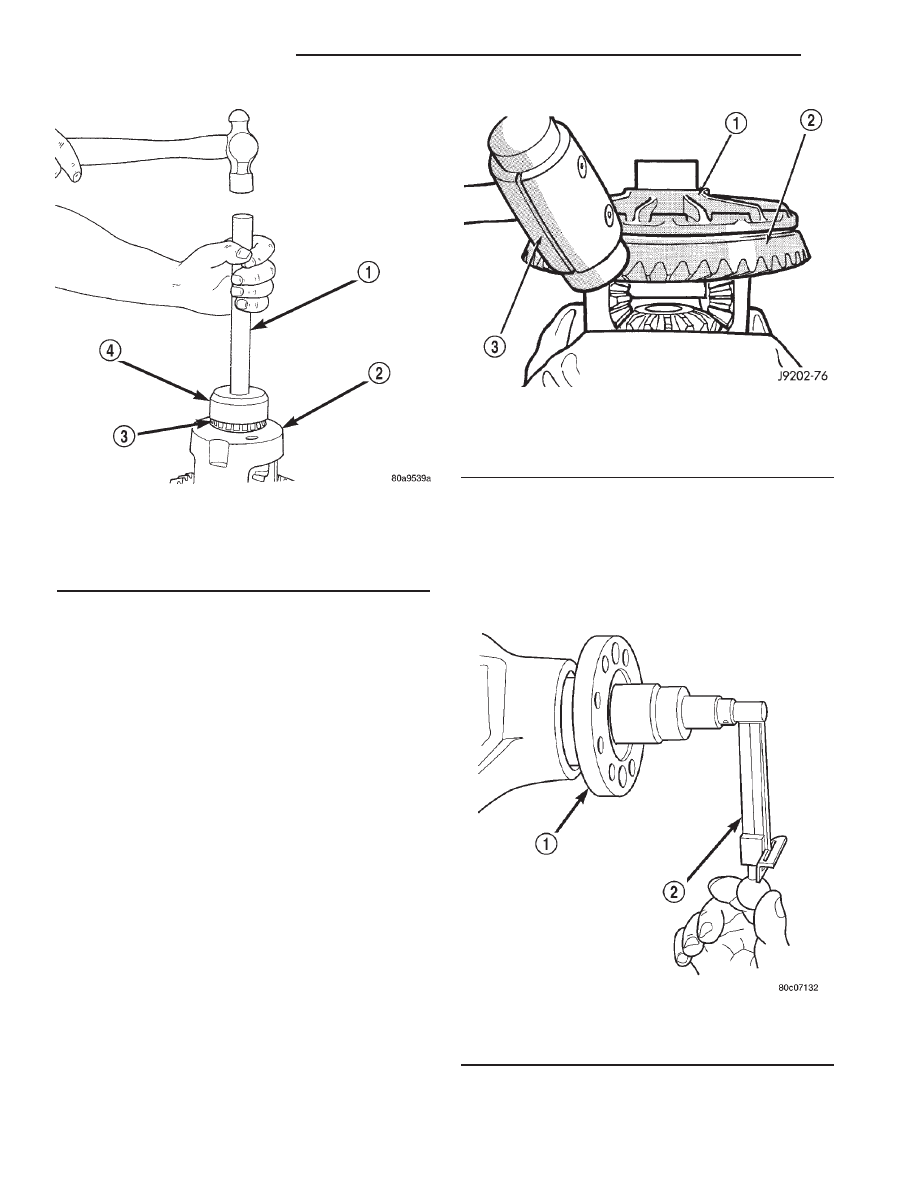
(2) Place differential case in a vise with soft jaw

(Fig. 30).

(3) Remove bolts holding ring gear to differential

case.

(4) Drive ring gear from differential case with a

soft hammer (Fig. 30).

(5) Mark the companion yoke and companion

flange for installation reference.

(6) Remove companion flange bolts and tie the pro-

peller shaft to the vehicle underbody.

(7) Rotate the companion flange three or four

times and verify flange rotates smoothly.

(8) Record rotating torque of the companion flange

with an inch pound torque wrench for installation
reference (Fig. 31).

(9) Install bolts into two of the threaded holes in

the companion flange 180° apart.

(10) Position Holder 6719 against the companion

flange and install a bolt and washer into one of the
remaining threaded holes. Tighten the bolts so that
the Holder 6719 is held to the flange.

(11) Remove the pinion nut.
(12) Remove the companion flange with Remover

C-452 (Fig. 32).

Fig. 29 Differential Side Bearings

1 - HANDLE
2 - DIFFERENTIAL
3 - BEARING
4 - INSTALLER

Fig. 30 Ring Gear

1 - DIFFERENTIAL CASE
2 - RING GEAR
3 - RAWHIDE HAMMER

Fig. 31 Pinion Rotating Torque

1 - COMPANION FLANGE
2 - INCH POUND TORQUE WRENCH

3 - 42

FRONT AXLE - C205F

AN

DIFFERENTIAL CASE BEARINGS (Continued)

(13) Remove pinion from differential housing (Fig.

33).

(14) Remove pinion seal with a pry tool or a slide

hammer mounted screw.

(15) Remove oil slinger, if equipped, and front pin-

ion bearing.

(16) Remove

front

pinion

bearing

cup

with

Remover D-103 and Handle C-4171 (Fig. 34).

(17) Remove rear bearing cup from housing (Fig.

35) with Remover 8401 and Handle C-4171.

Fig. 32 Companion Flange Remover

1 - COMPANION FLANGE
2 - PULLER TOOL

Fig. 33 Remove Pinion

1 - RAWHIDE HAMMER

Fig. 34 Front Bearing Cup

1 - REMOVER
2 - HANDLE

Fig. 35 Rear Bearing Cup

1 - DRIVER
2 - HANDLE

AN

FRONT AXLE - C205F

3 - 43

PINION GEAR/RING GEAR/TONE RING (Continued)

(18) Remove the collapsible preload spacer (Fig.

36).

(19) Remove rear pinion bearing with Puller/Press

C-293-PA and Adapters C-293-42 (Fig. 37).

(20) Remove depth shims from the pinion shaft

and record thickness of shims.

INSTALLATION

NOTE: The ring gear and pinion are serviced in a
matched set. Never replace one gear without replac-
ing the other. If ring and pinion gears or bearings
are replaced, Refer to Adjustments for Pinion Gear
Depth Setting.

(1) Apply Mopar Door Ease or equivalent lubricant

to outside surface of bearing cup.

(2) Install rear pinion bearing cup with Installer

D-145 and Driver Handle C-4171 (Fig. 38) and verify
cup is seated.

(3) Apply Mopar Door Ease or equivalent lubricant

to outside surface of bearing cup.

(4) Install front pinion bearing cup with Installer

D-129 and Handle C-4171 (Fig. 39) and verify cup is
seated.

(5) Install pinion front bearing and oil slinger if

equipped.

(6) Apply a light coating of gear lubricant on the

lip of pinion seal.

Fig. 36 Collapsible Spacer

1 - COLLAPSIBLE SPACER
2 - SHOULDER
3 - PINION
4 - PINION DEPTH SHIM
5 - REAR BEARING

Fig. 37 Rear Pinion Bearing

1 - SPECIAL TOOL C-293–PA
2 - VISE
3 - ADAPTERS
4 - DRIVE PINION GEAR SHAFT

Fig. 38 Rear Pinion Bearing Cup

1 - INSTALLER
2 - HANDLE

3 - 44

FRONT AXLE - C205F

AN

PINION GEAR/RING GEAR/TONE RING (Continued)

(7) Install pinion seal with Installer C-3972-A and

Handle C-4171 (Fig. 40).

(8) Place the proper thickness depth shim on the

pinion shaft.

(9) Install rear bearing and slinger if equipped,

onto the pinion shaft with Installer 6448 (Fig. 41)and
a press.

(10) Install newcollapsible preload spacer onto the

pinion shaft (Fig. 42).

(11) Install the pinion in the axle housing.
(12) Install the companion flange with Installer

C-3718 and Holder 6719.

(13) Install new pinion nut and tighten to 271 N·m

(200 ft. lbs.) (Fig. 43).

(14) Using Holder 6719 and a torque wrench set at

474 N·m (350 ft. lbs.). Tighten pinion nut until bear-
ing end play is taken up.

Fig. 39 Front Pinion Bearing Cup

1 - INSTALLER
2 - HANDLE

Fig. 40 Pinion Seal

1 - HANDLE
2 - INSTALLER

Fig. 41 Rear Pinion Bearing

1 - PRESS
2 - INSTALLER
3 - PINION GEAR
4 - REAR PINION BEARING

Fig. 42 Collapsible Preload Spacer

1 - COLLAPSIBLE SPACER
2 - SHOULDER
3 - PINION
4 - PINION DEPTH SHIM
5 - REAR BEARING

AN

FRONT AXLE - C205F

3 - 45

PINION GEAR/RING GEAR/TONE RING (Continued)


Content   ..  204  205  206  207   ..