Dodge Dakota (ND). Manual - part 955
P1684-BATTERY WAS DISCONNECTED (CONTINUED)
4.
(A919) FUSED B+ CIRCUIT
Turn the ignition off to the lock position.
Disconnect the PCM C1 harness connector.
NOTE: Check connectors - Clean/repair as necessary.
CAUTION: Do not probe the PCM harness connectors. Probing
the PCM harness connectors will damage the PCM terminals
resulting in poor terminal to pin connection. Install Miller Special
Tool #8815 to perform diagnosis.
Using a 12-volt test light connected to ground, check the (A919) Fused
B+ circuit.
NOTE: The test light must illuminate brightly. Compare the bright-
ness to that of a direct connection to the battery.
Does the test light illuminate brightly?
Yes
>> Go To 5
No
>> Repair the Fused B+ circuit for an open. If the fuse is
open make sure to check for a short to ground.
Perform 42RLE TRANSMISSION VERIFICATION TEST -
VER 1.
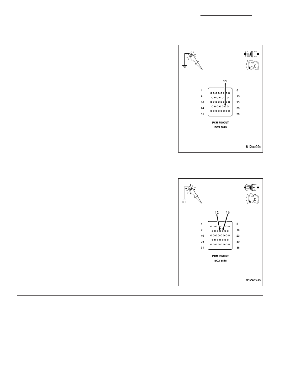
5.
(Z908) AND (Z977) GROUND CIRCUITS
Turn the ignition off to the lock position.
Disconnect the PCM C4 harness connector.
NOTE: Check connectors - Clean/repair as necessary.
Using a 12-volt test light connected to 12-volts, check the (Z908) and
(Z977) Ground circuits in the appropriate terminal of special tool
#8815.
NOTE: The test light must illuminate brightly. Compare the bright-
ness to that of a direct connection to the battery.
Does the test light illuminate brightly for all of the ground cir-
cuits?
Yes
>> Go To 6
No
>> Repair the Ground circuits for an open.
Perform 42RLE TRANSMISSION VERIFICATION TEST -
VER 1.
21 - 212
AUTOMATIC TRANSMISSION 42RLE - ELECTRICAL DIAGNOSTICS
ND