Dodge Dakota (ND). Manual - part 819


  Index      Dodge     Dodge Dakota (ND) 2005 - service repair manual 2005 year


Search            


Content   ..  817  818  819  820   ..


Dodge Dakota (ND). Manual - part 819


5. The valve seat and valve face must maintain a face angle of 44.5 - 45 ° angle.

REMOVAL

NOTE: The cylinder heads must be removed in
order to perform this procedure.

1. Remove rocker arms and lash adjusters (Refer to 9

-

ENGINE/CYLINDER

HEAD/ROCKER

ARM

/

ADJUSTER ASSY - REMOVAL).

2. Remove the camshaft bearing caps and the cam-

shaft.

NOTE: All six valve springs and valves are
removed in the same manner; this procedure only
covers one valve and valve spring.

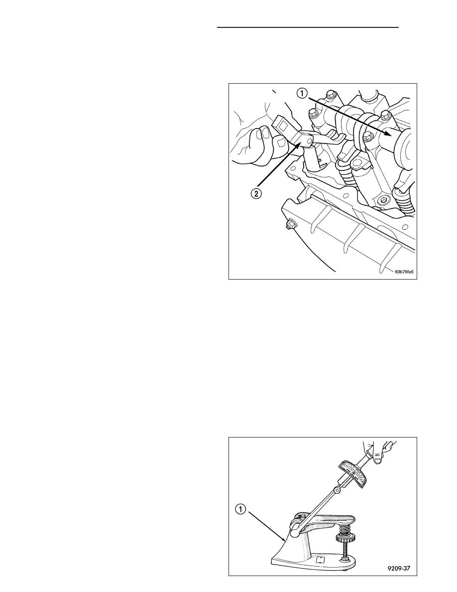
3. Using Tool C-3422–B or C-3422–C Valve Spring

Compressor and Tool 8519 Adapter (2), compress
the valve spring.

NOTE: It may be necessary to tap the top of the
valve spring to loosen the spring retainers locks
enough to be removed.

4. Remove the two spring retainer lock halves.

NOTE: the valve spring is under tension use care when releasing the valve spring compressor.

5. Remove the valve spring compressor (2).

6. Remove the spring retainer, and the spring.

NOTE: Check for sharp edges on the keeper grooves. Remove any burrs from the valve stem before remov-
ing the valve from the cylinder head.

7. Remove the valve from the cylinder head.

NOTE: The valve stem seals are common between intake and exhaust.

8. Remove the valve stem seal. Mark the valve for proper installation.

TESTING VALVE SPRINGS

NOTE: Whenever the valves are removed from the
cylinder head it is recommended that the valve
springs be inspected and tested for reuse.

Inspect the valve springs for physical signs of wear or
damage. Turn table of Tool C-647 (1) until surface is in
line with the 40.12 mm (1.579 in.) mark on the
threaded stud and the zero mark on the front. Place
spring over the stud on the table and lift compressing
lever to set tone device. Pull on torque wrench until a
Ping is heard. Take reading on torque wrench at this
instant. Multiply this reading by two. This will give the
spring load at test length. Fractional measurements
are indicated on the table for finer adjustments. Refer

9 - 814

ENGINE - 3.7L SERVICE INFORMATION

ND

to Specifications Section to obtain specified height and allowable tensions. Replace any springs that do not meet
specifications.

INSTALLATION

1. Coat the valve stem with clean engine oil and

insert it into the cylinder head.

2. Install the valve stem seal (3). Make sure the seal

is fully seated and that the garter spring at the top
of the seal is intact.

3. Install the spring and the spring retainer (2).

4. Using the valve spring compressor, compress the

spring (6) and install the two valve spring retainer
halves (1).

5. Release the valve spring compressor and make

sure the two spring retainer halves (1) and the
spring retainer (2) are fully seated.

6. Lubricate the camshaft journal with clean engine oil

then position the camshaft, with the sprocket dowel
on the left camshaft at 11 o’clock and the right
camshaft at 12 o’clock, then position the camshaft
bearing caps.

7. Install the camshaft bearing cap retaining bolts.

Tighten the bolts 9-13 N·m (100 in. lbs.) in 1/2 turn
increments in the sequence shown.

8. Position the hydraulic lash adjusters and rocker

arms (Refer to 9 - ENGINE/CYLINDER HEAD/
ROCKER ARM / ADJUSTER ASSY - INSTALLA-
TION).

ND

ENGINE - 3.7L SERVICE INFORMATION

9 - 815

ARM-ROCKER

DESCRIPTION

The rocker arms are steel stampings with an integral roller bearing. The rocker arms incorporate a 0.5 mm oil hole
in the lash adjuster socket for roller and camshaft lubrication.

REMOVAL

NOTE: Disconnect the battery negative cable to
prevent accidental starter engagement.

1. Remove the cylinder head cover (Refer to 9 -

ENGINE/CYLINDER

HEAD/CYLINDER

HEAD

COVER(S) - REMOVAL).

2. For rocker arm removal on cylinder No. 4, Rotate

the crankshaft until cylinder No. 1 is at BDC intake
stroke.

3. For rocker arm removal on cylinder No. 1, Rotate

the crankshaft until cylinder No. 1 is at BDC com-
bustion stroke.

4. For rocker arm removal on cylinders No. 3 and No.

5, Rotate the crankshaft until cylinder No. 1 is at
TDC exhaust stroke.

5. For rocker arm removal on cylinders No. 2 and No.

6, Rotate the crankshaft until cylinder No. 1 is at
TDC ignition stroke.

6. Using special Tool 8516 Rocker Arm Remover (2),

press downward on the valve spring, remove
rocker arm.

INSTALLATION

1. Using Tool 8516 (2) press downward on the valve spring, install rocker arm.

9 - 816

ENGINE - 3.7L SERVICE INFORMATION

ND

CAUTION: Make sure the rocker arms are installed
with the concave pocket over the lash adjusters.
Failure to do so may cause severe damage to the
rocker arms and/or lash adjusters.

NOTE: Coat the rocker arms with clean engine oil
prior to installation.

2. For rocker arm installation on cylinders No. 4,

Rotate the crankshaft until cylinder No. 1 is at BDC
intake stroke.

3. For rocker arm installation on cylinder No. 1,

Rotate the crankshaft until cylinder No. 1 is at BDC
combustion stroke.

4. For rocker arm installation on cylinders No. 3 and

No. 5, Rotate the crankshaft until cylinder No. 1 is
at TDC exhaust stroke.

5. For rocker arm installation on cylinders No. 2 and

No. 6, Rotate the crankshaft until cylinder No. 1 is
at TDC ignition stroke.

6. Install the cylinder head cover (Refer to 9 -

ENGINE/CYLINDER HEAD/CYLINDER HEAD COVER(S) - INSTALLATION).

SEALS-VALVE GUIDE

DESCRIPTION

The valve guide seals are made of rubber and incorporate an integral steel valve spring seat. The integral garter
spring maintains consistent lubrication control to the valve stems.

SPRINGS-VALVE

DESCRIPTION

The valve springs are made from high strength chrome silicon steel. The springs are NOT common for intake and
exhaust applications. The valve spring seat is integral with the valve stem seal, which is a positive type seal to
control lubrication.

REMOVAL

1. Remove the cylinder head cover (Refer to 9 - ENGINE/CYLINDER HEAD/CYLINDER HEAD COVER(S) -

REMOVAL).

2. Using Special Tool 8516 Valve Spring Compressor, remove the rocker arms and the hydraulic lash adjusters.

3. Remove the spark plug for the cylinder the valve spring and seal are to be removed from.

4. Apply shop air to the cylinder to hold the valves in place when the spring is removed.

NOTE: All six valve springs and seals are removed in the same manner; this procedure only covers one
valve seal and valve spring.

5. Using Special Tool 8387 Valve Spring Compressor, compress the valve spring.

NOTE: It may be necessary to tap the top of the valve spring to loosen the spring retainers locks enough to
be removed.

6. Remove the two spring retainer lock halves.

ND

ENGINE - 3.7L SERVICE INFORMATION

9 - 817


Content   ..  817  818  819  820   ..