Index Dodge Dodge Dakota (ND) 2005 - service repair manual 2005 year
Search
Content .. 355 356 357 358 ..
Dodge Dakota (ND). Manual - part 357
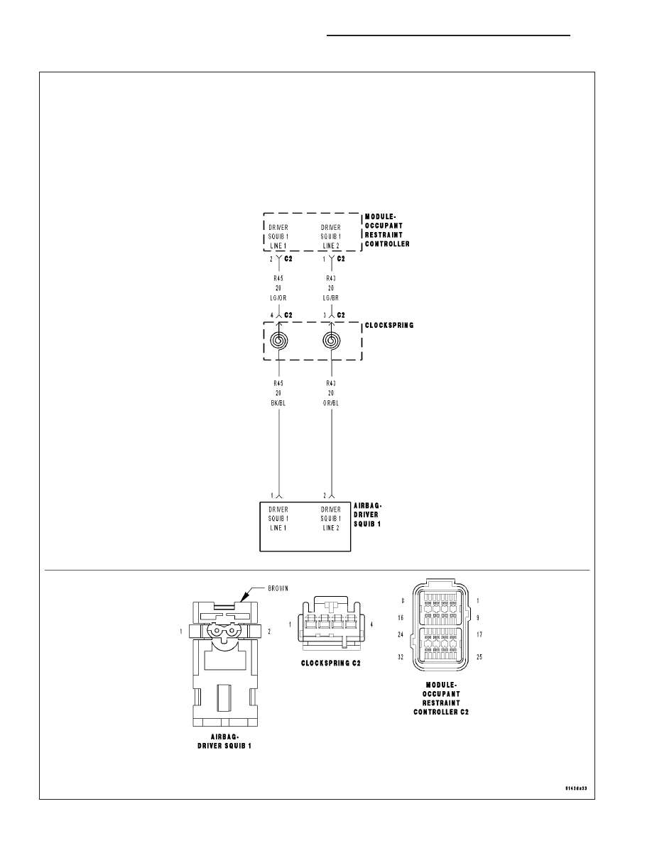
B1B01-DRIVER AIRBAG SQUIB 1 CIRCUIT HIGH
8O - 24
RESTRAINTS - ELECTRICAL DIAGNOSTICS
ND