Dodge Dakota (ND). Manual - part 329


  Index      Dodge     Dodge Dakota (ND) 2005 - service repair manual 2005 year


Search            


Content   ..  327  328  329  330   ..


Dodge Dakota (ND). Manual - part 329


COMPASS DEMAGNETIZING

A degaussing tool (Special Tool 6029) is used to
demagnetize, or degauss, the overhead console for-
ward mounting screw and the roof panel above the
overhead console. Equivalent units must be rated as
continuous duty for 110/115 volts and 60 Hz. They
must also have a field strength of over 350 gauss at 7
millimeters (0.25 inch) beyond the tip of the probe.

To demagnetize the roof panel and the overhead con-
sole forward mounting screw, proceed as follows:

1. Be certain that the ignition switch is in the Off position, before you begin the demagnetizing procedure.

2. Connect the degaussing tool to an electrical outlet, while keeping the tool at least 61 centimeters (2 feet) away

from the compass unit.

3. Slowly approach the head of the overhead console forward mounting screw with the degaussing tool connected.

4. Contact the head of the screw with the plastic coated tip of the degaussing tool for about two seconds.

5. With the degaussing tool still energized, slowly back it away from the screw. When the tip of the tool is at least

61 centimeters (2 feet) from the screw head, disconnect the tool.

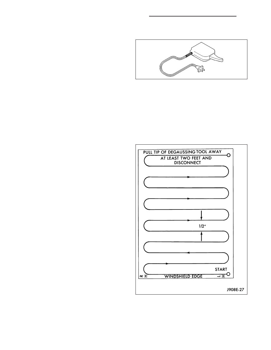
6. Place a piece of paper approximately 22 by 28

centimeters (8.5 by 11 inches), oriented on the
vehicle lengthwise from front to rear, on the center
line of the roof at the windshield header. The pur-
pose of the paper is to protect the roof panel from
scratches, and to define the area to be demagne-
tized.

7. Connect the degaussing tool to an electrical outlet,

while keeping the tool at least 61 centimeters (2
feet) away from the compass unit.

8. Slowly approach the center line of the roof panel at

the windshield header, with the degaussing tool
connected.

9. Contact the roof panel with the plastic coated tip of

the degaussing tool. Be sure that the template is in
place to avoid scratching the roof panel. Using a
slow, back-and-forth sweeping motion, and allowing
13 millimeters (0.50 inch) between passes, move
the tool at least 11 centimeters (4 inches) to each
side of the roof center line, and 28 centimeters (11
inches) back from the windshield header.

10. With the degaussing tool still energized, slowly

back it away from the roof panel. When the tip of
the tool is at least 61 centimeters (2 feet) from the
roof panel, disconnect the tool.

11. Calibrate the compass, (Refer to 8 - ELECTRI-

CAL/OVERHEAD

CONSOLE/COMPASS/MINI-

TRIP COMPUTER - STANDARD PROCEDURE -
COMPASS CALIBRATION) and adjust the compass variance, (Refer to 8 - ELECTRICAL/OVERHEAD CON-
SOLE/COMPASS/MINI-TRIP

COMPUTER

-

STANDARD

PROCEDURE

-

COMPASS

VARIATION

ADJUSTMENT).

8M - 22

OVERHEAD CONSOLE - SERVICE INFORMATION

ND

COMPASS VARIATION ADJUSTMENT

Compass variance, also known as magnetic declination, is the difference in angle between magnetic north and true
geographic north. In some geographic locations, the difference between magnetic and geographic north is great
enough to cause the compass to give false readings. If this problem occurs, the compass variance must be set.

To set the compass variance:

1. Using the Variance Settings map, find your geographic location and note the zone number.

2. Turn the ignition switch to the On/Run position. If the compass/temperature data is not currently being displayed,

momentarily depress and release the C/T push button to step through the display options until you have reached
the compass/temperature display.

3. Press and hold the Reset push button down until “VAR” appears in the display. This takes about five seconds.

4. Momentarily depress and release the STEP push button to step through the zone numbers (1-15), until the zone

number for your geographic location appears in the display.

5. Momentarily depress and release the Reset push button to enter the displayed zone number into the compass

unit memory.

6. Confirm that the correct directions are now indicated by the compass.

ND

OVERHEAD CONSOLE - SERVICE INFORMATION

8M - 23

REMOVAL

1. Disconnect and isolate the battery negative cable.

2. Remove the overhead console (3) from the head-

liner (Refer to 8 - ELECTRICAL/OVERHEAD CON-
SOLE - REMOVAL).

3. Remove the screws (1) that secure the Electronic

Overhead Module (EOM) (4) to the overhead con-
sole housing (3).

4. Disconnect the overhead console wire harness

connector from the EOM connector receptacle (2).

5. Remove the compass EOM (4) from the overhead

console housing (3).

INSTALLATION

NOTE: If a new Electronic overhead Module (EOM) has been installed, the compass will have to be cali-
brated and the variance set. (Refer to 8 - ELECTRICAL/OVERHEAD CONSOLE/COMPASS/MINI-TRIP COM-
PUTER - STANDARD PROCEDURE - COMPASS CALIBRATION) and (Refer to 8 - ELECTRICAL/OVERHEAD
CONSOLE/COMPASS/MINI-TRIP COMPUTER - STANDARD PROCEDURE - COMPASS VARIATION ADJUST-
MENT) for the appropriate procedures.

1. Position the Electronic overhead Module (EOM) (4)

onto the overhead console housing (3).

2. Reconnect the overhead console wire harness con-

nector to the EOM connector receptacle (2).

3. Install the screws (1) that secure the EOM (4) to

the overhead console housing (3). Tighten the
screws to 2.2 N·m (20 in. lbs.).

4. Install the overhead console (3) onto the headliner

(Refer to 8 - ELECTRICAL/OVERHEAD CONSOLE
- INSTALLATION).

5. Reconnect the battery negative cable.

8M - 24

OVERHEAD CONSOLE - SERVICE INFORMATION

ND

UNIVERSAL TRANSMITTER

DESCRIPTION

The universal transmitter transceiver is integral to the
overhead console (7). The only visible component of
the universal transmitter are the three transmitter push
buttons (3). The buttons are marked with one, two or
three dots, respectively, for identification of each chan-
nel.

Each of the three universal transmitter push buttons
controls an independent radio transmitter channel.
Each of these three channels can be trained to trans-
mit a different radio frequency signal for the remote
operation of garage door openers, motorized gate
openers, home or office lighting, security systems or
just about any other device that can be equipped with
a radio receiver in the 286 to 399 MegaHertz (MHz)
frequency range for remote operation. The universal
transmitter is capable of operating systems using
either rolling code or non-rolling code technology.

The universal transmitter cannot be repaired, and is
available for service only as part of the Electronic
Overhead Module (EOM). This unit includes the push button switches for both the transmitter and compass mini trip
computer, The Vacuum-Fluorescent Display (VFD) and the plastic module case. (Refer to 8 - ELECTRICAL/OVER-
HEAD CONSOLE/COMPASS/MINI-TRIP COMPUTER - REMOVAL) for EOM replacement.

OPERATION

The universal transmitter operates on a non-switched source of battery current so the unit will remain functional,
regardless of the ignition switch position. It can learn and store three separate transmitter radio frequency codes to
operate garage door openers, security gates and security lighting. The overhead console display provides visual
feedback to the driver, showing which transmitter button is pressed. The system will not send operating signals if the
vehicle theft security alarm is armed. This prevents a perpetrator from breaking into a vehicle parked outside a
home and using the transmitter system to enter the home.

ND

OVERHEAD CONSOLE - SERVICE INFORMATION

8M - 25


Content   ..  327  328  329  330   ..