Dodge Dakota (ND). Manual - part 269


  Index      Dodge     Dodge Dakota (ND) 2005 - service repair manual 2005 year


Search            


Content   ..  267  268  269  270   ..


Dodge Dakota (ND). Manual - part 269


B2107–IGNITION SWITCH SENSE INPUT CIRCUIT/PERFORMANCE (CONTINUED)

12.

CHECK (F961) IGNITION SWITCH OUTPUT (RUN) CIRCUIT FOR A SHORT TO GROUND

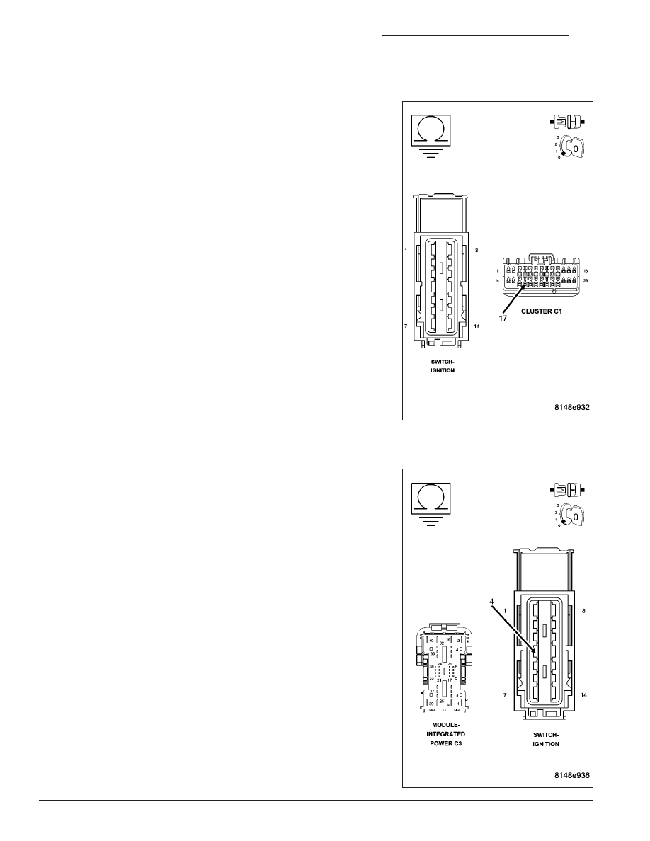
Disconnect the Instrument Cluster C1 harness connector.

Disconnect the ignition switch harness connector.

Measure the resistance between ground and the (F924) Ignition
Switch Output (RUN) circuit.

Is the resistance below 10K ohms?

YES

>> Repair the (F961) Ignition Switch Output (RUN) circuit for

a short to ground.

Perform the BODY VERIFICATION TEST-VER 1. (Refer to
8 - ELECTRICAL/ELECTRONIC CONTROL MODULES/
FRONT CONTROL MODULE - DIAGNOSIS AND TEST-
ING)

NO

>> Go To 13

13.

CHECK (A923) FUSED B+ CIRCUIT FOR A SHORT TO GROUND

Disconnect the IPM C3 harness connector.

Disconnect the Ignition Switch harness connector.

Measure the resistance between ground and the (A923) Fused B+ cir-
cuit.

Is the resistance below 10K ohms?

YES

>> Repair the (A923) Fused B+ circuit for a short to ground.

Perform the BODY VERIFICATION TEST-VER 1. (Refer to
8 - ELECTRICAL/ELECTRONIC CONTROL MODULES/
FRONT CONTROL MODULE - DIAGNOSIS AND TEST-
ING)

NO

>> Go To 14

8J - 18

INSTRUMENT CLUSTER - ELECTRICAL DIAGNOSTICS

ND

B2107–IGNITION SWITCH SENSE INPUT CIRCUIT/PERFORMANCE (CONTINUED)

14.

CHECK CIRCUITS F901, F941, FOR A SHORT TO GROUND

Remove JB fuses: 8, 36.

Using the wiring diagrams, measure the resistance between ground
and the F901 and F941 circuits.

Is the resistance below 10K ohms on any one of these circuits?

YES

>> Repair the appropriate circuit for a short to ground.

Perform the BODY VERIFICATION TEST-VER 1. (Refer to
8 - ELECTRICAL/ELECTRONIC CONTROL MODULES/
FRONT CONTROL MODULE - DIAGNOSIS AND TEST-
ING)

NO

>> Replace the Ignition Switch in accordance with the service

information.

Perform the BODY VERIFICATION TEST-VER 1. (Refer to
8 - ELECTRICAL/ELECTRONIC CONTROL MODULES/
FRONT CONTROL MODULE - DIAGNOSIS AND TEST-
ING)

15.

CHECK CIRCUIT (A953) FOR A SHORT TO GROUND

Disconnect the IPM C3 harness connector.

Disconnect the Ignition Switch harness connector

Using the wiring diagrams, measure the resistance between ground
and the (A953) circuit.

Is the resistance below 10K ohms?

YES

>> Repair circuit (A953) for a short to ground.

Perform the BODY VERIFICATION TEST-VER 1. (Refer to
8 - ELECTRICAL/ELECTRONIC CONTROL MODULES/
FRONT CONTROL MODULE - DIAGNOSIS AND TEST-
ING)

NO

>> Go To 16

ND

INSTRUMENT CLUSTER - ELECTRICAL DIAGNOSTICS

8J - 19

B2107–IGNITION SWITCH SENSE INPUT CIRCUIT/PERFORMANCE (CONTINUED)

16.

CHECK CIRCUIT (F982) FOR A SHORT TO GROUND

Remove IPM fuse #55.

Using the wiring diagrams, measure the resistance between ground
and the (F982) circuit.

Is the resistance below 10K ohms?

YES

>> Repair circuit (F982) for a short to ground.

Perform the BODY VERIFICATION TEST-VER 1. (Refer to
8 - ELECTRICAL/ELECTRONIC CONTROL MODULES/
FRONT CONTROL MODULE - DIAGNOSIS AND TEST-
ING)

NO

>> Replace the Ignition Switch in accordance with the service

information.

Perform the BODY VERIFICATION TEST-VER 1. (Refer to
8 - ELECTRICAL/ELECTRONIC CONTROL MODULES/
FRONT CONTROL MODULE - DIAGNOSIS AND TEST-
ING)

8J - 20

INSTRUMENT CLUSTER - ELECTRICAL DIAGNOSTICS

ND

B2213–CABIN COMPARTMENT NODE/CLUSTER INTERNAL

For a complete wiring diagram Refer to Section 8W.

When Monitored:
With the ignition on.

Set Condition:
The Instrument Cluster detects an internal failure.

Possible Causes

INSTRUMENT CLUSTER

Diagnostic Test

1.

VERIFY INSTRUMENT CLUSTER OPERATION

NOTE: When this DTC is active and the Instrument Cluster Backlighting is inoperative, the Instrument Clus-
ter must be replaced.

Is DTC: B2213–CABIN COMPARTMENT NODE/CLUSTER INTERNAL active AND the Instrument Cluster
Backlighting inoperative?

YES

>> Replace the Instrument Cluster in accordance with the service information.

Perform the BODY VERIFICATION TEST-VER 1. (Refer to 8 - ELECTRICAL/ELECTRONIC CONTROL
MODULES/FRONT CONTROL MODULE - DIAGNOSIS AND TESTING)

NO

>> Disregard DTC, test complete.

ND

INSTRUMENT CLUSTER - ELECTRICAL DIAGNOSTICS

8J - 21


Content   ..  267  268  269  270   ..