Dodge Dakota (ND). Manual - part 251


  Index      Dodge     Dodge Dakota (ND) 2005 - service repair manual 2005 year


Search            


Content   ..  249  250  251  252   ..


Dodge Dakota (ND). Manual - part 251


HEATER-CUSHION PAD

DESCRIPTION

Vehicles equipped with the optional heated seat system have two, carbon fiber heated seat elements, located in
each front seat. One heating element is used for each seat cushion and another for each seat back.

Each of the heated seat element consists of multiple heating circuits operating in parallel throughout the carbon fiber
element. The heated seat elements are captured between the leather trim cover and the seat cushion assembly. If
a malfunction occurs in one or more of the individual carbon fiber circuits, the others will continue to provide heat.

The heated seat elements cannot be repaired. If found to be damaged or inoperative, a new heating element
assembly must be installed.

OPERATION

One end of the heated seat element is connected to ground at all times through a splice under the seat. Battery
current is directed to the other end of the heated seat element by the heated seat module. The heated seat module
will energize the heated seat element when the heated seat switch is depressed in the Low or High position.

As electrical current passes through the heated seat element, the resistance of the wire used in the element dis-
perses some of the electrical current in the form of heat. The heat produced by the heated seat element then radi-
ates through the underside of the seat cushion and seat back trim covers, warming the seat cover and its occupant.

DIAGNOSIS AND TESTING

HEATED SEAT ELEMENT

Refer to the appropriate wiring information for
complete circuit schematic or connector pin-out
information.

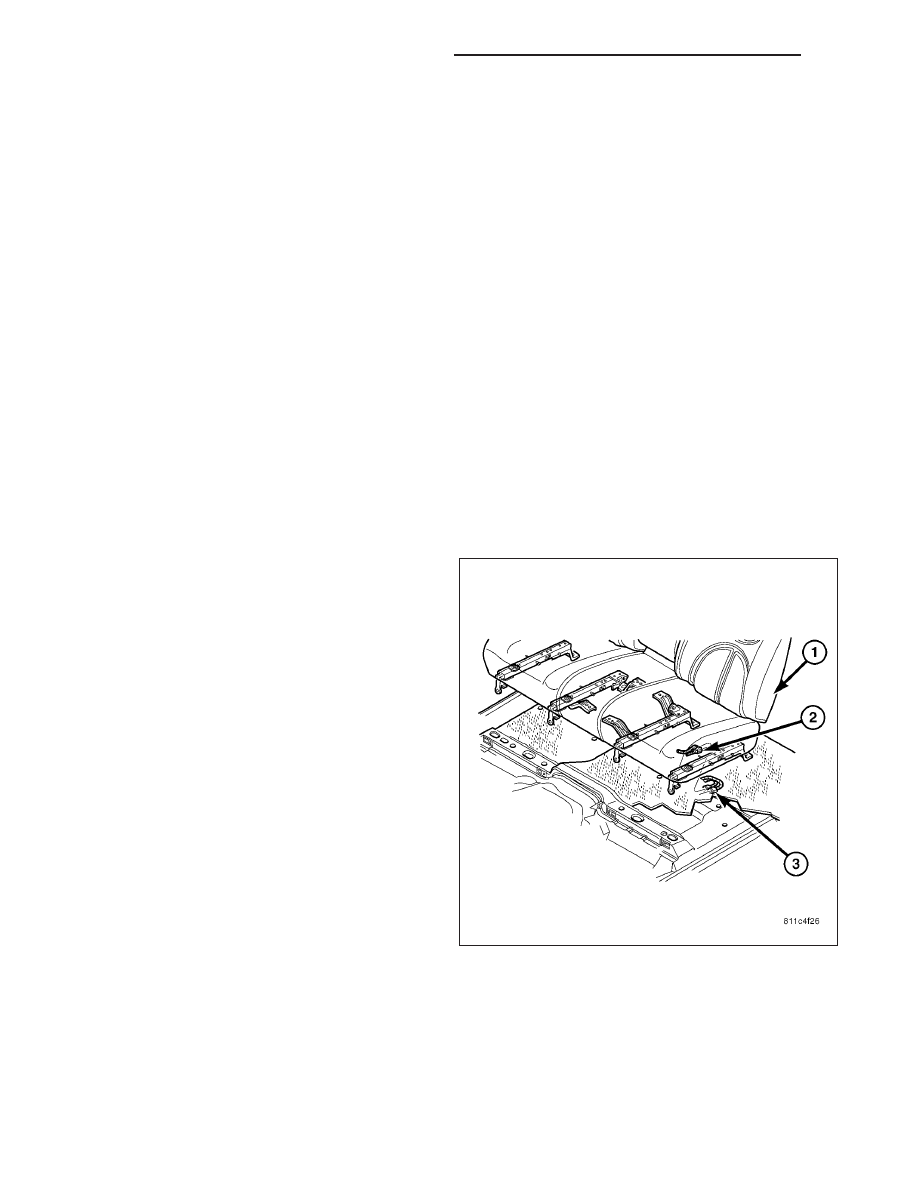
The wire harness connectors (2&3) for the heating
elements are located under the seat (1).

NOTE: When checking heated seat elements for
continuity, be certain to move the heating element
being checked. Moving the element, such as sit-
ting in the seat will eliminate the possibility of an
intermittent open in the element which would only
be evident if the element was in a certain position.
Failure to check the element in various positions
could result in an incomplete test.

1. Locate and disconnect the seat electrical connec-

tor.

2. Check the resistance between the circuit leading in

and out of the suspect heated seat element. The
resistance should be between 3.8 - 4.8 ohms for a
seat cushion element and 4.3 - 5.4 ohms for a seat
back element. If OK, (Refer to 8 - ELECTRICAL/
HEATED SEATS - DIAGNOSIS AND TESTING). If not OK, replace the inoperative heated seat element.

8G - 22

HEATED SEATS - SERVICE INFORMATION

ND

REMOVAL

NOTE: Do not remove the factory installed heating
elements (3) from the seat or seat back cushions.
The original element is permanently attached and
cannot be removed without permanent damage.
The replacement heating element is designed to
be applied directly on top of the inoperative fac-
tory installed heating element.

1. Disconnect and isolate the negative battery cable.

2. Remove the appropriate seat cushion, (Refer to 23

-

BODY/SEATS/SEAT

CUSHION

COVER

-

REMOVAL) or seat back trim cover, (Refer to 23 -
BODY/SEATS/SEAT BACK CUSHION / COVER -
REMOVAL).

3. Disconnect the inoperative heated seat cushion or

seat back element electrical connectors (2).

4. Locate the wires leading from the inoperative heat-

ing element and cut them off flush with the edge of
the original heating element.

INSTALLATION

1. Peel off the adhesive backing on the back of the

replacement heating element (2) and stick directly
on top of the factory installed heating element (1).

CAUTION: During the installation of the replace-
ment heating element, be careful not to fold or
crease the element assembly. Folds or creases will
cause premature failure.

ND

HEATED SEATS - SERVICE INFORMATION

8G - 23

2. Connect the new heating element electrical con-

nectors (3&4).

3. Connect the battery negative cable.

4. Verify heated seat system operation.

5. Install the appropriate seat cushion, (Refer to 23 -

BODY/SEATS/SEAT CUSHION COVER - INSTAL-
LATION) or seat back trim cover, (Refer to 23 -
BODY/SEATS/SEAT BACK CUSHION / COVER -
INSTALLATION).

NOTE: Make certain the seat wire harness is cor-
rectly routed through the seat and seat back. The
excess wire between the cushion and back ele-
ments should be securely tucked between the rear
of the cushion foam and the rear carpet flap of the
trim cover.

MODULE-HEATED SEAT

DESCRIPTION

The heated seat module (4) is an electronic micropro-
cessor controlled device designed and programmed to
use inputs from the heated seat relay, the two heated
seat switches and the two heated seat sensors to
operate and control the heated seat elements in both
front seats and the two heated seat indicator lamp
Light-Emitting Diodes (LEDs) in each heated seat
switch. The heated seat module is also programmed
to perform self-diagnosis of certain heated seat sys-
tem functions and provide feedback of that diagnosis
through the heated seat switch indicator lamps.

The heated seat module (4) is mounted inside the
center floor console (5) on the backside of the power
outlet panel (3). The heated seat module has a single
connector receptacle that allows the module to be
connected to all of the required inputs and outputs
through the seat wire harness.

The heated seat module cannot be repaired. If the
heated seat module is damaged or inoperative, the
entire module must be replaced.

OPERATION

The heated seat module operates on fused battery current received from a fuse in the Integrated Power Module
(IPM). The module is grounded at all times. Inputs to the module include a resistor multiplexed heated seat switch
request circuit for each of the two heated seat switches and the heated seat sensor inputs from the seat cushions
of each front seat. In response to those inputs, the heated seat module controls battery current to the heated seat
elements and sensors, and controls the ground for the heated seat switch indicator lamps (LED’s).

8G - 24

HEATED SEATS - SERVICE INFORMATION

ND

When a heated seat switch (Driver or Passenger) is depressed a signal is received by the heated seat module, the
module energizes the proper indicator LED (Low or High) in the switch by grounding the indicator lamp circuit to
indicate that the heated seat system is operating. At the same time, the heated seat module energizes the selected
heated seat sensor circuit and the sensor provides the module with an input indicating the surface temperature of
the selected seat cushion.

The Low heat set point is about 36° C (96.8° F), and the High heat set point is about 42° C (107.6° F). If the seat
cushion surface temperature input is below the temperature set point for the selected temperature setting, the
heated seat module energizes an N-channel Field Effect Transistor (N-FET) within the module which energizes the
heated seat elements in the selected seat cushion and back. When the sensor input to the module indicates the
correct temperature set point has been achieved, the module de-energizes the N-FET which de-energizes the
heated seat elements. The heated seat module will continue to cycle the N-FET as needed to maintain the selected
temperature set point.

If the heated seat module detects a heated seat sensor value input that is out of range or a shorted or open heated
seat element circuit, it will communicate this condition by flashing the High and/or Low indicator lamps in the
affected heated seat switch. (Refer to 8 - ELECTRICAL/HEATED SEATS - DIAGNOSIS AND TESTING) for flashing
LED diagnosis and testing procedures.

DIAGNOSIS AND TESTING

HEATED SEAT MODULE

NOTE: Before testing the individual components in the heated seat system, check the vehicles battery
open-circuit voltage and charging system performance. If the vehicles electrical system is defective or weak
it may not be suppling sufficient energy to operate the heated seat system.

If a heated seat fails to heat and one or both of the indicator lamps on a heated seat switch flash, (Refer to 8 -
ELECTRICAL/HEATED SEATS - DIAGNOSIS AND TESTING) for flashing LED diagnosis and testing procedures-
.For complete circuit diagrams, refer to the appropriate wiring information. The wiring information includes
wiring diagrams, proper wire and connector repair procedures, details of wire harness routing and retention, con-
nector pin-out information and location views for the various wire harness connectors, splices and grounds.

1. Remove the heated seat module from its mounting location (Refer to 8 - ELECTRICAL/HEATED SEATS/

HEATED SEAT MODULE - REMOVAL).

NOTE: ANY RESISTANCE VALUES (OHMS

V

) GIVEN IN THE FOLLOWING TEXT ARE SUPPLIED USING THE

AUTOMATIC RANGE GENERATED BY A FLUKE

T

AUTOMOTIVE METER. IF ANOTHER TYPE OF MEASURING

DEVICE IS USED THE VALUES GENERATED MAY NOT BE THE SAME AS THE RESULTS SHOWN HERE, OR
MAY HAVE TO BE CONVERTED TO THE RANGE USED HERE.

ND

HEATED SEATS - SERVICE INFORMATION

8G - 25


Content   ..  249  250  251  252   ..