Dodge Dakota (ND). Manual - part 239


  Index      Dodge     Dodge Dakota (ND) 2005 - service repair manual 2005 year


Search            


Content   ..  237  238  239  240   ..


Dodge Dakota (ND). Manual - part 239


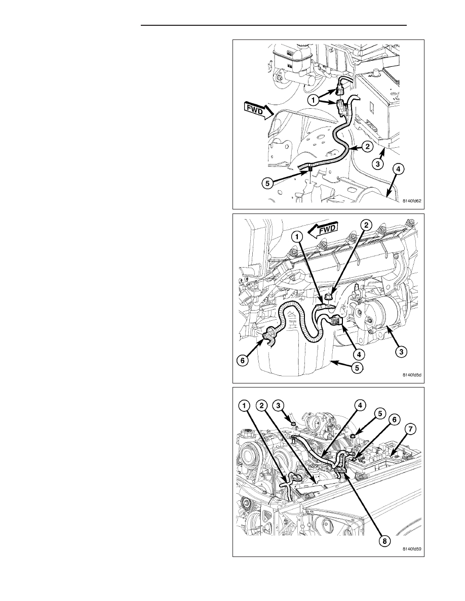
4. Install the cable (5) pushpin into the left frame rail

(4).

5. Connect the starter solenoid wire harness connec-

tor (1).

6. Raise the vehicle on a hoist, (Refer to LUBRICA-

TION & MAINTENANCE/HOISTING - STANDARD
PROCEDURE).

7. Install the nut (2) securing the cable (1) to the

starter solenoid (3).

8. Connect the battery cable retaining pushpin (6)

securing the cable to the engine block.

9. Lower the vehicle.

10. Connect the battery positive cable terminal clamp

(8).

8F - 26

BATTERY SYSTEM

ND

11. Position the resonator (4) into the vehicle. Install

the bolts (3) into the air intake resonator (4) and
tighten the band clamp (2) on the air inlet tube (1).

12. Connect

the

battery

negative

cable

terminal

clamp.

13. Check the vehicle for normal operation.

BATTERY TRAY

DESCRIPTION

The molded plastic battery tray (3) is located in the left
front corner of the engine compartment. On this vehi-
cle, the battery tray also provides an anchor point for
the anti-lock brake controller (4), battery temperature
sensor (2) and the Integrated Power Module (IPM) (1).
The battery hold down hardware is contained within
the battery tray. A hole in the bottom of the battery tray
is fitted with a battery temperature sensor. (Refer to 8
-

ELECTRICAL/CHARGING/BATTERY

TEMPERA-

TURE SENSOR - DESCRIPTION) for additional infor-
mation on the battery temperature sensor.

ND

BATTERY SYSTEM

8F - 27

REMOVAL

1. Disconnect and isolate the battery negative cable.

2. Remove the battery, (Refer to 8 - ELECTRICAL/

BATTERY SYSTEM/BATTERY - REMOVAL).

3. Remove the battery temperature sensor (2) from

the battery tray (3), (Refer to 8 - ELECTRICAL/
CHARGING/BATTERY TEMPERATURE SENSOR -
REMOVAL).

4. Remove the Integrated Power Module (IPM) (1),

(Refer to 8 - ELECTRICAL/POWER DISTRIBU-
TION/INTEGRATED

POWER

MODULE

-

REMOVAL).

5. Remove the Antilock Brake System (ABS) Hydrau-

lic Control Unit (HCU) (3) bolts (2) from the battery
tray (1).

6. Remove the battery negative cable retaining push-

pins (5) from the battery tray.

8F - 28

BATTERY SYSTEM

ND

7. Remove the engine compartment wire harness

retaining pushpins (3) from the battery tray (2).

8. Remove the left headlamp assembly, (Refer to 8 -

ELECTRICAL/LAMPS/LIGHTING

-

EXTERIOR/

HEADLAMP UNIT - REMOVAL).

9. Remove the battery tray bolts.

10. Remove the six upper battery tray bolts.

ND

BATTERY SYSTEM

8F - 29


Content   ..  237  238  239  240   ..