Dodge Dakota (ND). Manual - part 224
*NO RESPONSE FROM WCM (SENTRY KEY REMOTE ENTRY MODULE) (CONTINUED)
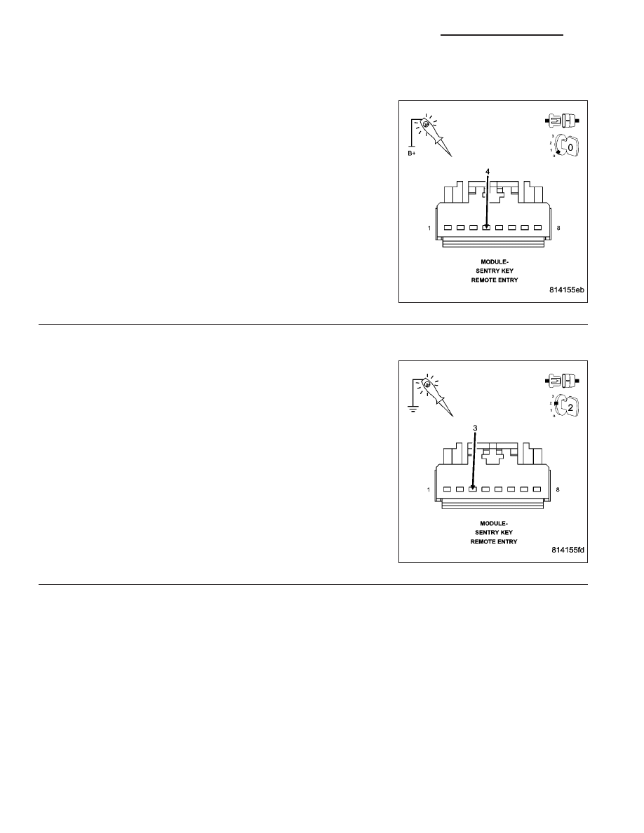
3.
(Z109) GROUND CIRCUIT OPEN
Using a 12-volt test light connected to 12-volts, check the (Z109)
ground circuit.
Does the test light illuminate brightly?
Yes
>> Go To 4
No
>> Repair the (Z109) ground circuit for an open.
Perform SKREEM VERIFICATION TEST
4.
(F202) FUSED IGNITION SWITCH OUTPUT CIRCUIT OPEN OR SHORTED
Turn the ignition on.
Using a 12-volt test light connected to ground, check the (F202) Fused
Ignition Switch Output circuit.
Does the test light illuminate brightly?
Yes
>> Go To 5
No
>> Repair the (F202) Fused Ignition Switch Output circuit for
an open or short.
Perform SKREEM VERIFICATION TEST
8E - 152
ELECTRONIC CONTROL MODULES - ELECTRICAL DIAGNOSTICS
ND