Dodge Dakota (ND). Manual - part 182


  Index      Dodge     Dodge Dakota (ND) 2005 - service repair manual 2005 year


Search            


Content   ..  180  181  182  183   ..


Dodge Dakota (ND). Manual - part 182


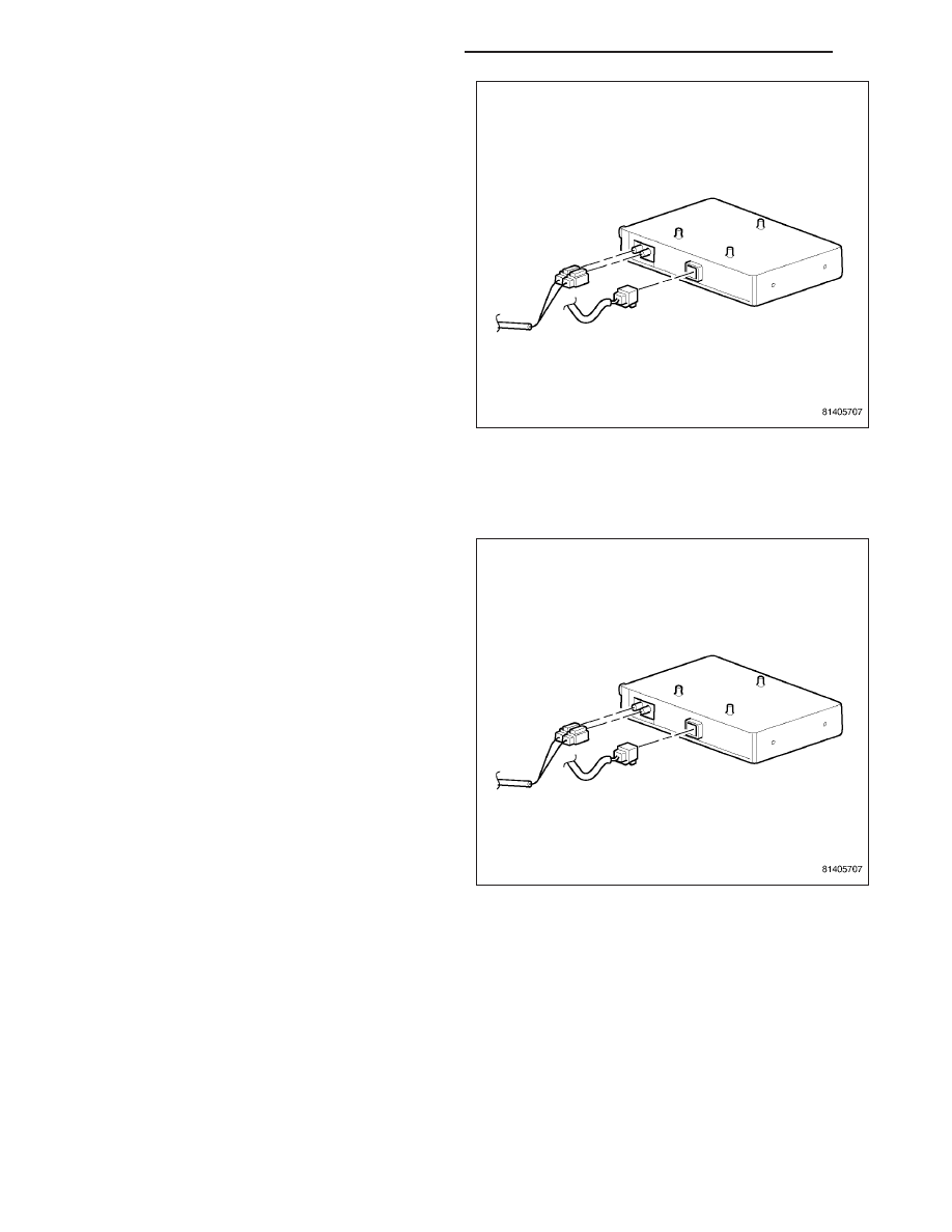
4. Disconnect the antenna and electrical harness con-

nectors. Remove the module.

INSTALLATION

CLUB CAB

1. Connect antenna and electrical harness connector

to module.

8A - 186

AUDIO/VIDEO - SERVICE INFORMATION

ND

2. Position module and install mounting fasteners.

Tighten fasteners.

3. Lower carpet into position.

4. Install the left side door scuff plate.

5. Connect battery negative cable.

QUAD CAB

1. Connect antenna and electrical harness connector

to module.

ND

AUDIO/VIDEO - SERVICE INFORMATION

8A - 187

2. Position module and install mounting fasteners.

Tighten fasteners.

3. Lower the left rear seat.

4. Connect battery negative cable.

SPEAKER

DESCRIPTION

STANDARD

The standard equipment speaker system includes speakers in four locations. One 16.5 centimeter (6.5 inch) diam-
eter speaker is located in each front door. One 16.5 centimeter (6.5 inch) diameter speaker is located in each rear
door on quad cab vehicles. One 16.5 centimeter (6.5 inch) diameter speaker is located in each C-pillar on club cab
vehicles.

INFINITY

The infinity speaker system includes speakers in six locations. One 16.5 centimeter (6.5 inch) diameter speaker is
located in each front door. One 16.5 centimeter (6.5 inch) diameter speaker located in each rear door on quad cab
vehicles. One 16.5 centimeter (6.5 inch) diameter speaker is located in each C-pillar on club cab vehicles. A 19
millimeter tweeter is mounted high in each front door trim panel. The infinity speaker system includes an amplifier
located on the right side cowl panel. The total available power of the infinity speaker system is 288 watts.

DIAGNOSIS AND TESTING

SPEAKER

Any diagnosis of the Audio system should begin with the use of a scan tool and the appropriate Diagnostic
Service information.

Refer to the appropriate wiring information.

WARNING: DISABLE THE AIRBAG SYSTEM BEFORE ATTEMPTING ANY STEERING WHEEL, STEERING
COLUMN, SEAT BELT TENSIONER, SIDE AIRBAG, OR INSTRUMENT PANEL COMPONENT DIAGNOSIS OR
SERVICE. DISCONNECT AND ISOLATE THE BATTERY NEGATIVE (GROUND) CABLE, THEN WAIT TWO MIN-
UTES FOR THE AIRBAG SYSTEM CAPACITOR TO DISCHARGE BEFORE PERFORMING FURTHER DIAGNO-
SIS OR SERVICE. THIS IS THE ONLY SURE WAY TO DISABLE THE AIRBAG SYSTEM. FAILURE TO TAKE
THE PROPER PRECAUTIONS COULD RESULT IN ACCIDENTAL AIRBAG DEPLOYMENT AND POSSIBLE
PERSONAL INJURY.

CAUTION: The speaker output of the radio is a “floating ground” system. Do not allow any speaker lead to
short to ground, as damage to the radio may result.

8A - 188

AUDIO/VIDEO - SERVICE INFORMATION

ND

1. If all speakers are inoperative, check the radio fuses in the Integrated Power Module (IPM). If OK, go to Step 2.

If not OK, repair the shorted circuit or component as required and replace the faulty fuse.

2. Check the amplifier fuse (if equipped) in the Integrated Power Module (IPM). If OK, go to Step 3. If not OK,

repair the shorted circuit or component as required and replace the faulty fuse.

3. Turn the ignition switch to the ON position. Turn the radio receiver ON. Adjust the balance and fader control

controls to check the performance of each individual speaker. Note the speaker locations that are not performing
correctly. Go to Step 4.

4. Turn the radio OFF. Turn the ignition OFF. Disconnect and isolate the battery negative cable. If vehicle is not

equipped with a amplifier, remove the radio receiver. If the vehicle is equipped with an amplifier, disconnect the
two wire harness connectors. Go to Step 5.

5. Check both the speaker feed (+) circuit and return (-) circuit cavities for the inoperative speaker at the wire har-

ness connector for continuity to ground. There should be no continuity. If OK, go to Step 6. If not OK, repair the
shorted speaker feed (+) and/or return (-) circuits(s) to the speaker as required.

6. Disconnect wire harness connector at the inoperative speaker. Check for continuity between the speaker feed (+)

circuit cavities of the radio receiver wire harness connector or if equipped, the amplifier wire harness connector
and the speaker wire harness connector. Repeat the check between the speaker return (-) circuit cavities of the
radio receiver wire harness connector and the speaker wire harness connector. In each case, there should be
continuity. If OK, replace the faulty speaker. If not OK, repair the open speaker feed (+) and/or return (-) cir-
cuits(s) as required.

REMOVAL

SPEAKER - FRONT DOOR

1. Disconnect and isolate the battery negative cable.

2. Remove the front door trim panel (Refer to 23 -

BODY/DOOR - FRONT/TRIM PANEL - REMOVAL).

3. Remove the mounting fasteners.

ND

AUDIO/VIDEO - SERVICE INFORMATION

8A - 189


Content   ..  180  181  182  183   ..