Dodge Dakota (ND). Manual - part 131


  Index      Dodge     Dodge Dakota (ND) 2005 - service repair manual 2005 year


Search            


Content   ..  129  130  131  132   ..


Dodge Dakota (ND). Manual - part 131


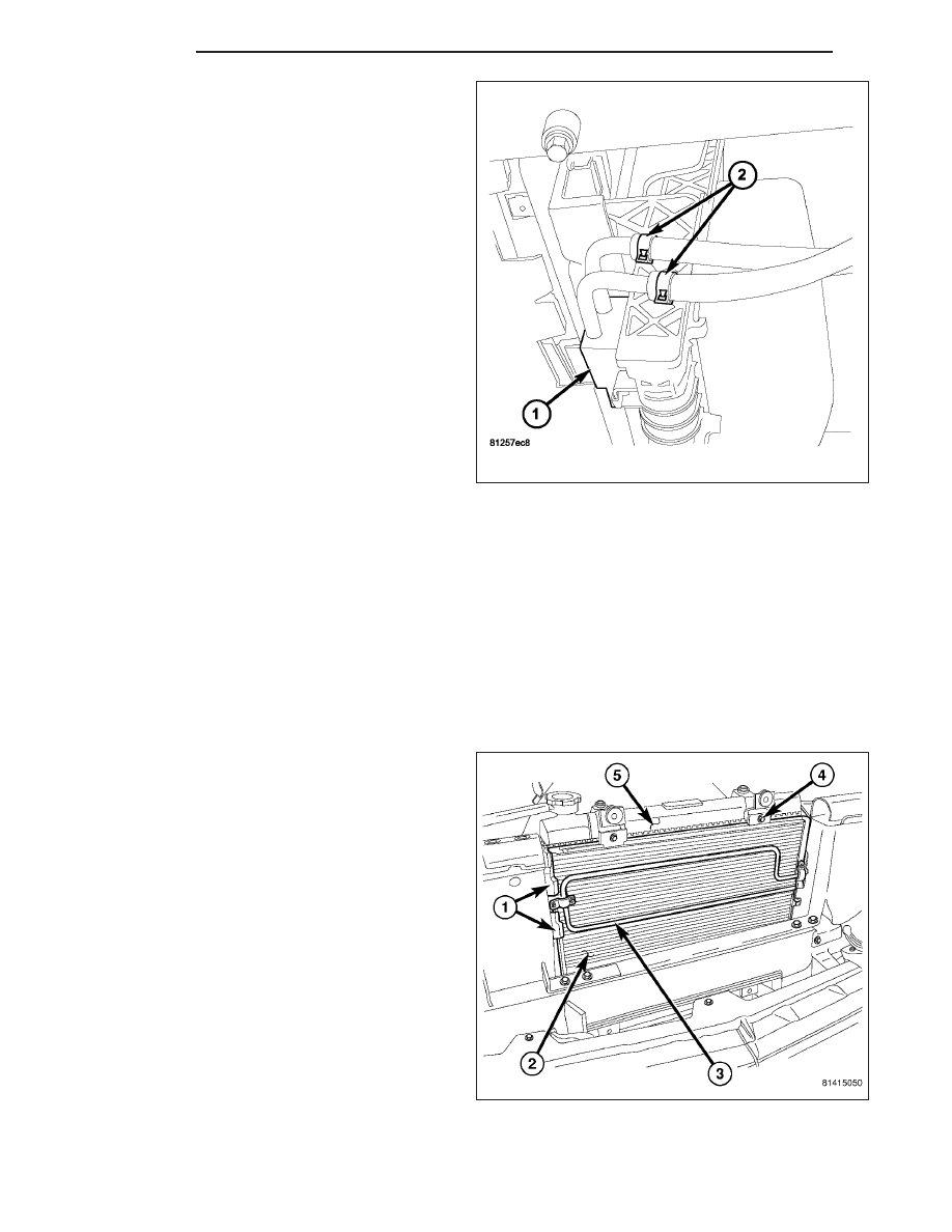
9. Disconnect the power steering cooler lines (2).

10. Remove the lower radiator hose.

11. Lower vehicle.

12. Remove upper radiator mounting bolts.

13. Remove radiator.

14. Remove

power

steering

fluid/transmission

oil

cooler form the radiator, if necessary.

CLEANING

Clean radiator fins With the engine cold, apply cold water and compressed air to the back (engine side) of the
radiator to flush the radiator and/or A/C condenser of debris.

INSPECTION

The radiator cooling fins should be checked for damage or deterioration. Inspect cooling fins to make sure they are
not bent or crushed, these areas result in reduced heat exchange causing the cooling system to operate at higher
temperatures. Inspect the plastic end tanks for cracks, damage or leaks.

Inspect the radiator neck for damage or distortion.

INSTALLATION

The radiator has two isolator pins on bottom of both
tanks. These fit into alignment holes in radiator lower
support.

1. Install power steering cooler, if removed.

2. Install transmission oil cooler if removed.

3. Install the upper radiator mount

4. Position isolator pins into alignment holes in radia-

tor lower support.

5. Install upper radiator support. Tighten bolts to 23

N·m (200 in. lbs.)

6. Install LH and RH radiator side seals.

7. Install upper radiator hose.

8. Install overflow tube.

9. Install radiator shroud.

7 - 36

ENGINE

ND

10. Install power steering cooler lines.

11. Install transmission cooler lines.

12. Install lower radiator hose.

13. Lower vehicle.

14. Fill radiator (Refer to 7 - COOLING - STANDARD

PROCEDURE).

15. Connect battery negative cable.

16. Start and warm the engine. Check for leaks.

CAP-RADIATOR PRESSURE

DESCRIPTION

All cooling systems are equipped with a pressure cap
on the radiator. This cap releases pressure at some
point within a range of 131-to-158 kPa (19-to-23 psi).
The pressure relief point (in pounds) is engraved on
top of the cap (3).

The cooling system will operate at pressures slightly
above atmospheric pressure. This results in a higher
coolant boiling point allowing increased radiator cool-
ing capacity. The cap contains a spring-loaded pres-
sure relief valve (4). This valve opens when system
pressure reaches the release range of 131-to-158 kPa
(19-to-23 psi).

A rubber gasket (2) seals the radiator filler neck. This
is done to maintain vacuum during coolant cool-down
and to prevent leakage when system is under
pressure.

ND

ENGINE

7 - 37

OPERATION

A vent valve in the center of the cap will remain shut as long as the cooling system is pressurized. As the coolant
cools, it contracts and creates a vacuum in cooling system. This causes the vacuum valve to open and coolant in
reserve/overflow tank to be drawn through connecting hose into radiator. If the vacuum valve is stuck shut, or over-
flow hose is kinked, radiator hoses will collapse on cool-down.

DIAGNOSIS AND TESTING

RADIATOR CAP-TO-FILLER NECK SEAL

The pressure cap upper gasket (seal) pressure relief can be tested by removing overflow hose from radiator filler
neck nipple. Attach hose of pressure tester tool 7700 (or equivalent) to nipple. It will be necessary to disconnect
hose from its adapter for filler neck. Pump air into radiator. The pressure cap upper gasket should relieve at 131
kPa (21 psi) and hold pressure at a minimum of 130 kPa (18.8 psi).

WARNING: THE WARNING WORDS “DO NOT OPEN HOT” ON RADIATOR PRESSURE CAP, ARE A SAFETY
PRECAUTION. WHEN HOT, PRESSURE BUILDS UP IN COOLING SYSTEM. TO PREVENT SCALDING OR
INJURY, RADIATOR CAP SHOULD NOT BE REMOVED WHILE SYSTEM IS HOT AND/OR UNDER PRESSURE.

Do not remove radiator cap at any time except for the following purposes:

1. Check and adjust antifreeze freeze point.

2. Refill system with new antifreeze.

3. Conducting service procedures.

4. Checking for vacuum leaks.

WARNING: IF VEHICLE HAS BEEN RUN RECENTLY, WAIT AT LEAST 15 MINUTES BEFORE REMOVING
RADIATOR CAP. WITH A RAG, SQUEEZE RADIATOR UPPER HOSE TO CHECK IF SYSTEM IS UNDER PRES-
SURE. PLACE A RAG OVER CAP AND WITHOUT PUSHING CAP DOWN, ROTATE IT COUNTER-CLOCKWISE
TO FIRST STOP. ALLOW FLUID TO ESCAPE THROUGH THE COOLANT RESERVE/OVERFLOW HOSE INTO
RESERVE/OVERFLOW TANK. SQUEEZE RADIATOR UPPER HOSE TO DETERMINE WHEN PRESSURE HAS
BEEN RELEASED. WHEN COOLANT AND STEAM STOP BEING PUSHED INTO TANK AND SYSTEM PRES-
SURE DROPS, REMOVE RADIATOR CAP COMPLETELY.

RADIATOR CAP

Remove cap (1) from radiator. Be sure that sealing
surfaces are clean. Moisten rubber gasket with water
and install cap (1) on pressure tester 7700 (2) or an
equivalent.

Operate tester pump to bring pressure to 138 kPa (20
psi) on gauge. If pressure cap (1) fails to hold pres-
sure of at least 131 kPa (19 psi) replace cap. Refer to
the following CAUTION .

The pressure cap may test properly while positioned
on tool 7700 (or equivalent). It may not hold pressure
or vacuum when installed on radiator. If so, inspect
radiator filler neck and cap’s top gasket for damage.
Also inspect for dirt or distortion that may prevent cap
from sealing properly.

7 - 38

ENGINE

ND

CAUTION: Radiator pressure testing tools are very sensitive to small air leaks, which will not cause cooling
system problems. A pressure cap that does not have a history of coolant loss should not be replaced just
because it leaks slowly when tested with this tool. Add water to tool. Turn tool upside down and recheck
pressure cap to confirm that cap needs replacement.

CLEANING

Use only a mild soap and water to clean the radiator cap. Using any type solvent may cause damage to the seal
in the radiator cap.

INSPECTION

Hold cap at eye level, right side up. The vent valve at bottom of cap should open. If rubber gasket has swollen and
prevents vent valve from opening, replace cap.

Hold cap at eye level, upside down. If any light can be seen between vent valve and rubber gasket, replace cap. Do
not use a replacement cap that has a spring to hold vent shut. 
A replacement cap must be the type designed
for a coolant reserve/overflow system with a completely sealed diaphragm spring and a rubber gasket. This gasket
is used to seal to radiator filler neck top surface. Use of proper cap will allow coolant return to radiator.

PUMP-WATER

DESCRIPTION

WATER PUMP

A centrifugal water pump (1) circulates coolant through
the water jackets, passages, intake manifold, radiator
core, cooling system hoses and heater core. The
pump is driven from the engine crankshaft by a single
serpentine drive belt that drives the water pump pulley
(1).

The water pump impeller is pressed onto the rear of a
shaft that rotates in bearings pressed into the housing.
The housing has two small holes to allow seepage to
escape. The water pump seals are lubricated by the
antifreeze in the coolant mixture. No additional lubrica-
tion is necessary.

Both heater hoses are connected to fittings on the tim-
ing chain front cover. The water pump is also mounted
directly to the timing chain cover and is equipped with
a non serviceable integral pulley.

ND

ENGINE

7 - 39


Content   ..  129  130  131  132   ..