Dodge Dakota (ND). Manual - part 1296


  Index      Dodge     Dodge Dakota (ND) 2005 - service repair manual 2005 year


Search            


Content   ..  1294  1295  1296  1297   ..


Dodge Dakota (ND). Manual - part 1296


8. Disconnect the charging station and manifold gauge set from the refrigerant system service ports.

9. Reinstall the caps onto the refrigerant system service ports.

ACCUMULATOR-A/C

DESCRIPTION

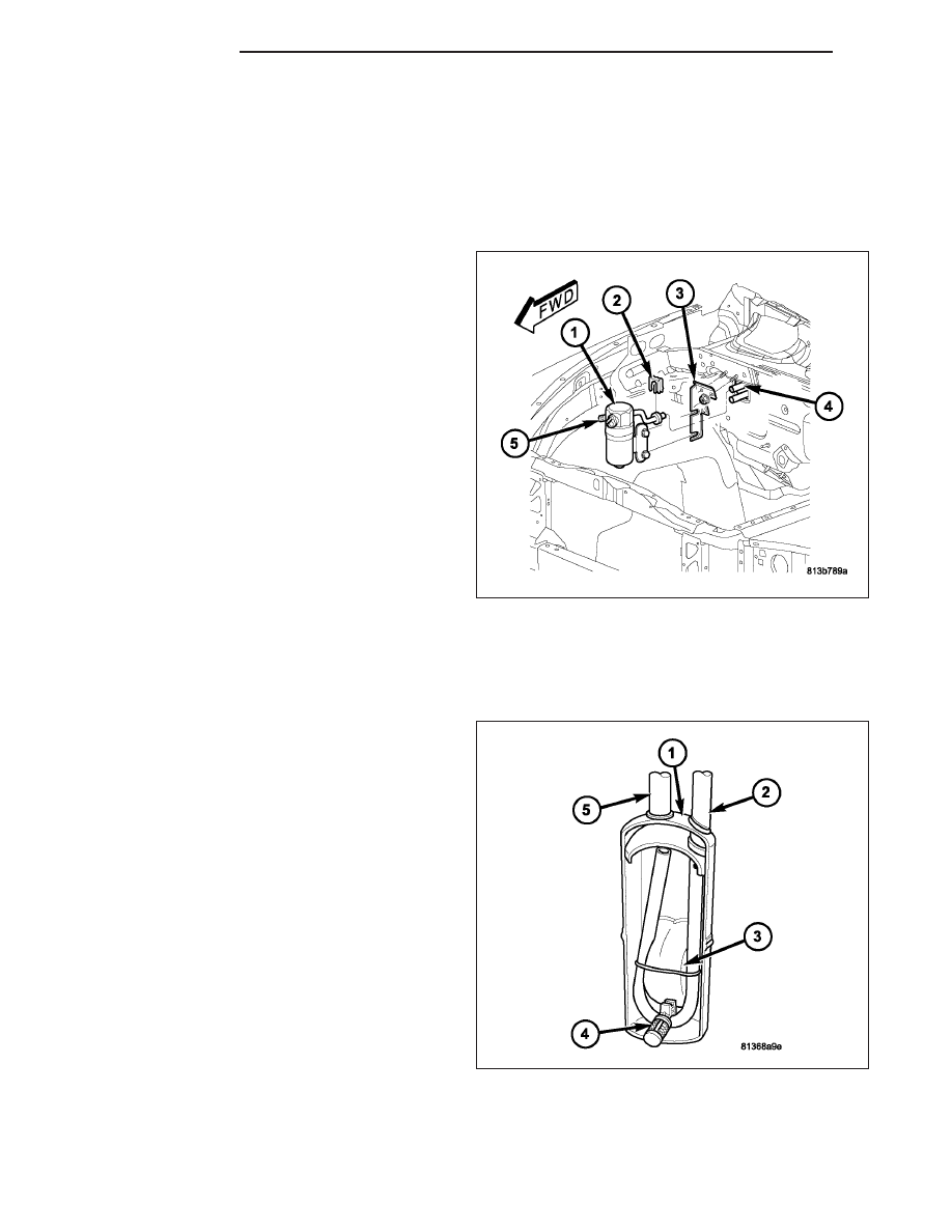
The A/C accumulator (1) is mounted in the engine
compartment between the evaporator outlet tube (4)
and the A/C suction line and includes the low- side
service port (5). An integral mounting bracket secures
the accumulator to the dash panel bracket (3). A
spring-lock type quick-connect fitting is used to con-
nect the accumulator to the evaporator outlet tube.

CAUTION: Use only O-ring seals specified for the
vehicle. Failure to use the correct O-ring seals will
cause the refrigerant system connections to leak.

The A/C accumulator has no serviceable parts except
for the rubber O-ring seals, gasket, low-side service
port valve and cap and the secondary retaining clip
(2). The O-ring seals used on the connections are
made from a special type of rubber not affected by
R-134a refrigerant. The O-ring seals and gasket must
be

replaced

whenever

the

A/C

accumulator

is

removed and installed.

The A/C accumulator cannot be repaired and, if faulty or damaged, it must be replaced.

OPERATION

NOTE: Typical A/C accumulator shown.

Refrigerant enters the A/C accumulator (1) mostly as a
low pressure vapor through the inlet tube (2). Any liq-
uid, oil-laden refrigerant falls to the bottom of the can-
ister, which acts as a separator. A desiccant bag (3) is
mounted inside the accumulator canister to absorb
any moisture which may have entered and become
trapped within the refrigerant system A filter (4) is also
mounted inside the canister to trap any foreign mate-
rial that may have entered the refrigerant system dur-
ing assembly. The low pressure vapor exits the A/C
accumulator through the outlet tube (5).

The A/C accumulator cannot be repaired. If the A/C
accumulator is faulty or damaged, or if the refrigerant
system has been contaminated or left open to the
atmosphere for an indeterminable period or if the A/C
compressor has failed, it must be replaced.

24 - 182

PLUMBING

ND

REMOVAL

WARNING: Review the warnings and cautions in the front of this section before performing the following
operation (Refer to 24 - HEATING & AIR CONDITIONING/PLUMBING - WARNINGS) and (Refer to 24 - HEAT-
ING & AIR CONDITIONING/PLUMBING - CAUTIONS).

1. Disconnect and isolate the negative battery cable.

2. Recover the refrigerant from the refrigerant system

(Refer to 24 - HEATING & AIR CONDITIONING/
PLUMBING

-

STANDARD

PROCEDURE

-

REFRIGERANT SYSTEM RECOVERY).

3. Remove the air filter housing to gain access to the

A/C accumulator (1) (Refer to 9 - ENGINE/AIR
INTAKE SYSTEM).

4. Disconnect the A/C suction line from the A/C accu-

mulator and remove and discard the O-ring and
gasket (Refer to 24 - HEATING & AIR CONDI-
TIONING/PLUMBING/LINE-A/C

SUCTION

-

REMOVAL).

5. Remove the secondary retaining clip (2) from the

spring-lock coupler that secures the accumulator
inlet tube to the evaporator outlet tube (5).

6. Loosen the bolts (6) that secure the A/C accumu-

lator to the mounting bracket (4).

7. Using the proper A/C line disconnect tool, disconnect the accumulator inlet tube from the evaporator outlet tube

(Refer to 24 - HEATING & AIR CONDITIONING/PLUMBING/COUPLER-REFRIGERANT LINE - REMOVAL) and
remove and discard the O-ring seals.

8. Install plugs in, or tape over the opened refrigerant system connections.

9. If required, remove the nuts (3) that secure the accumulator mounting bracket to the dash panel and remove the

bracket from the engine compartment.

INSTALLATION

NOTE: If the A/C accumulator is being replaced, add 60 milliliters (2 fluid ounces) of refrigerant oil to the
refrigerant system. Use only refrigerant oil of the type recommended for the A/C compressor in the vehicle.

1. If

removed,

install

the

accumulator

mounting

bracket (4) and retaining nuts (3). Tighten the nuts
to 4.5 N·m (40 in. lbs.).

2. Position the A/C accumulator (1) onto the mounting

bracket. Do not tighten the accumulator bracket
bolts (6) at this time.

3. Remove the tape or plugs from the opened refrig-

erant system connections.

4. Lubricate new rubber O-ring seals with clean refrig-

erant oil and install them onto the accumulator
spring-lock coupler fitting. Use only the specified
O-rings as they are made of a special material for
the R-134a system. Use only refrigerant oil of the
type recommended for the A/C compressor in the
vehicle.

5. Connect the spring-lock coupler to the evaporator

outlet tube (5) and install the secondary retaining

ND

PLUMBING

24 - 183

clip (3) (Refer to 24 - HEATING & AIR CONDITIONING/PLUMBING/COUPLER-REFRIGERANT LINE - INSTAL-
LATION).

6. Tighten the accumulator bracket bolts to 4.5 N·m (40 in. lbs.).

7. Connect the A/C suction line to the A/C accumulator (Refer to 24 - HEATING & AIR CONDITIONING/PLUMB-

ING/SUCTION LINE - INSTALLATION).

8. Install the air filter housing (Refer to 9 - ENGINE/AIR INTAKE SYSTEM).

9. Evacuate the refrigerant system (Refer to 24 - HEATING & AIR CONDITIONING/PLUMBING - STANDARD PRO-

CEDURE - REFRIGERANT SYSTEM EVACUATE).

10. Charge the refrigerant system (Refer to 24 - HEATING & AIR CONDITIONING/PLUMBING - STANDARD PRO-

CEDURE - REFRIGERANT SYSTEM CHARGE).

11. Reconnect the negative battery cable.

COMPRESSOR-A/C

DESCRIPTION

A/C COMPRESSOR

The A/C system uses a Denso 10S17 reciprocating
swash plate-type compressor (1). This A/C compres-
sor has a fixed displacement of 170 cubic centimeters
(10.374) and has both the suction and discharge ports
(2) located on the cylinder head (3) at the rear of the
compressor.

A label identifying the use of R-134a refrigerant is
located on the A/C compressor.

HIGH PRESSURE RELIEF VALVE

A high pressure relief valve is located on the compressor cylinder head, which is at the rear of the A/C compressor.
This mechanical valve is designed to vent refrigerant from the A/C system to protect against damage to the A/C
compressor and other A/C system components, caused by condenser air flow restriction or an overcharge of
refrigerant.

OPERATION

A/C COMPRESSOR

The A/C compressor is driven by the engine through an electric clutch, drive pulley and belt arrangement. The A/C
compressor is lubricated by refrigerant oil that is circulated throughout the refrigerant system with the refrigerant.

The A/C compressor draws in low-pressure refrigerant vapor from the A/C evaporator through its suction port. It then
compresses the refrigerant into a high-pressure, high-temperature refrigerant vapor, which is then pumped to the
A/C condenser through the compressor discharge port.

24 - 184

PLUMBING

ND

The A/C compressor cannot be repaired and, if faulty or damaged, it must be replaced. The compressor clutch,
pulley and bearing assembly, and clutch field coil are available for service.

HIGH PRESSURE RELIEF VALVE

The high pressure relief valve vents refrigerant from the A/C system when a discharge pressure of 3445 to 4135
kPa (500 to 600 psi) or above is reached. The high pressure relief valve closes with a minimum discharge pressure
of 2756 kPa (400 psi) is reached.

The high pressure relief valve vents only enough refrigerant to reduce the A/C system pressure, and then re-seats
itself. The majority of the refrigerant is conserved in the A/C system. If the high pressure relief valve vents refrig-
erant, it does not mean the valve is faulty.

The high pressure relief valve is factory-calibrated and cannot be adjusted or repaired, and must not be removed or
otherwise disturbed. The valve is only serviced as a part of the A/C compressor.

DIAGNOSIS AND TESTING

A/C COMPRESSOR

When investigating an A/C system related noise, you must first know the conditions under which the noise occurs.
These conditions include: weather, vehicle speed, transmission in gear or neutral, engine speed, engine tempera-
ture, and any other special conditions. Noises that develop during A/C operation can often be misleading. For exam-
ple: What sounds like a failed front engine bearing or connecting rod, may be caused by loose bolts, nuts, mounting
brackets or a loose compressor clutch assembly.

Drive belts are speed sensitive. At different engine speeds and depending upon drive belt tension, drive belts can
develop noises that are mistaken for an A/C compressor noise. Improper drive belt tension can cause a misleading
noise when the compressor clutch is engaged, which may not occur when the compressor clutch is disengaged.
Check the accessory drive belt condition and tension as described in Cooling before beginning this procedure.

1. Select a quiet area for testing. Duplicate the complaint conditions as much as possible. Turn the A/C compressor

On and Off several times to clearly identify the compressor noise. Listen to the A/C compressor while the clutch
is engaged and disengaged. Probe the A/C compressor with an engine stethoscope or a long screwdriver with
the handle held to your ear to better localize the source of the noise.

2. Loosen all of the compressor mounting hardware and retighten. Check the compressor clutch retainer. Be certain

that the clutch field coil is mounted securely to the A/C compressor, and that the clutch plate and pulley are
properly aligned and have the correct air gap (Refer to 24 - HEATING & AIR CONDITIONING/CONTROLS/
CLUTCH-A/C COMPRESSOR - INSTALLATION).

3. To duplicate high-ambient temperature conditions (high head pressure), restrict the air flow through the A/C con-

denser. Install a manifold gauge set or a scan tool to be certain that the discharge pressure does not exceed
2760 kPa (400 psi).

4. Check the refrigerant system plumbing for incorrect routing, rubbing or interference, which can cause unusual

noises. Also check the refrigerant lines and hoses for kinks or sharp bends that will restrict refrigerant flow, which
can cause noises (Refer to 24 - HEATING & AIR CONDITIONING/PLUMBING - DESCRIPTION - REFRIGER-
ANT LINES)

5. If the noise is from opening and closing of the high pressure relief valve, recover, evacuate and recharge the

refrigerant system (Refer to 24 - HEATING & AIR CONDITIONING/PLUMBING - STANDARD PROCEDURE -
REFRIGERANT SYSTEM RECOVERY), (Refer to 24 - HEATING & AIR CONDITIONING/PLUMBING - STAN-
DARD PROCEDURE - REFRIGERANT SYSTEM EVACUATE) and (Refer to 24 - HEATING & AIR CONDITION-
ING/PLUMBING - STANDARD PROCEDURE - REFRIGERANT SYSTEM CHARGE). If the high pressure relief
valve still does not seat properly, replace the A/C compressor (Refer to 24 - HEATING & AIR CONDITIONING/
PLUMBING/COMPRESSOR-A/C - REMOVAL).

6. If the noise is from liquid refrigerant slugging in the A/C suction line, replace the A/C accumulator (Refer to 24 -

HEATING & AIR CONDITIONING/PLUMBING/ACCUMULATOR-A/C - REMOVAL) and check the refrigerant oil
level and the refrigerant system charge (Refer to 24 - HEATING & AIR CONDITIONING/PLUMBING/REFRIG-
ERANT OIL - STANDARD PROCEDURE - REFRIGERANT OIL LEVEL) (Refer to 24 - HEATING & AIR CON-
DITIONING/PLUMBING- STANDARD PROCEDURE - REFRIGERANT SYSTEM CHARGE).

7. If a slugging condition still exists after replacing the A/C accumulator, then replace the A/C compressor (Refer to

24 - HEATING & AIR CONDITIONING/PLUMBING/COMPRESSOR-A/C - REMOVAL) and repeat Step 1.

ND

PLUMBING

24 - 185


Content   ..  1294  1295  1296  1297   ..