Dodge Dakota (ND). Manual - part 1294


  Index      Dodge     Dodge Dakota (ND) 2005 - service repair manual 2005 year


Search            


Content   ..  1292  1293  1294  1295   ..


Dodge Dakota (ND). Manual - part 1294


INSTALLATION

1. Position the blower motor (2) into the HVAC hous-

ing (4).

2. Install the three screws (3) that secure the blower

motor to the HVAC housing. Tighten the screws to
2 N·m (17 in. lbs.).

3. Connect the wire harness connector (1) to the

blower motor.

4. Reconnect the negative battery cable.
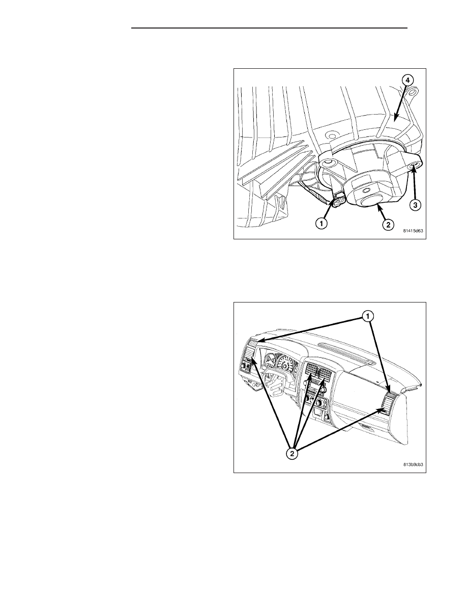
OUTLET-AIR

DESCRIPTION

There are two side window demister air outlets (1).
One located at each end of the instrument panel near
the A-pillars. The airflow from the side window demis-
ter air outlets is directed by fixed vanes in the demis-
ter outlet grilles and cannot be adjusted. The side
window demister air outlets are only serviced with the
instrument panel air outlets.

There are four instrument panel air outlets (2). One air
outlet is located near each outboard end of the instru-
ment panel facing the rear of the vehicle and two air
outlets are located at the top of the instrument panel
center bezel. Each of the instrument panel air outlets
contain a grille with movable vanes that are used to
direct or shut off the flow of the conditioned air leaving
the instrument panel outlets. The instrument panel air
outlets and grilles cannot be serviced separately
(Refer to 23 - BODY/INSTRUMENT PANEL/CLUSTER
BEZEL - REMOVAL), (Refer to 23 - BODY/INSTRU-
MENT

PANEL/INSTRUMENT

PANEL

CENTER

BEZEL - REMOVAL) and (Refer to 23 - BODY/IN-
STRUMENT PANEL/IP PASSENGER SIDE BEZEL - REMOVAL).

24 - 174

DISTRIBUTION

ND

PLUMBING

TABLE OF CONTENTS

page

page

PLUMBING

DESCRIPTION

. . . . . . . . . . . . . . . . . . . . . . . . 175

OPERATION

. . . . . . . . . . . . . . . . . . . . . . . . . . 176

WARNING

WARNINGS

. . . . . . . . . . . . . . . . . . . . . . . . . 176

CAUTION

CAUTIONS

. . . . . . . . . . . . . . . . . . . . . . . . . 177

DIAGNOSIS AND TESTING

REFRIGERANT SYSTEM LEAKS

. . . . . . . . . 178

STANDARD PROCEDURE

REFRIGERANT SYSTEM SERVICE

EQUIPMENT . . . . . . . . . . . . . . . . . . . . . . . . 179

REFRIGERANT SYSTEM RECOVERY

. . . . . 180

REFRIGERANT SYSTEM EVACUATE

. . . . . 180

REFRIGERANT SYSTEM CHARGE

. . . . . . . 181

ACCUMULATOR-A/C

DESCRIPTION

. . . . . . . . . . . . . . . . . . . . . . . . 182

OPERATION

. . . . . . . . . . . . . . . . . . . . . . . . . . 182

REMOVAL

. . . . . . . . . . . . . . . . . . . . . . . . . . . . 183

INSTALLATION

. . . . . . . . . . . . . . . . . . . . . . . . 183

COMPRESSOR-A/C

DESCRIPTION

A/C COMPRESSOR

. . . . . . . . . . . . . . . . . . . 184

HIGH PRESSURE RELIEF VALVE

. . . . . . . . 184

OPERATION

A/C COMPRESSOR

. . . . . . . . . . . . . . . . . . . 184

HIGH PRESSURE RELIEF VALVE

. . . . . . . . 185

DIAGNOSIS AND TESTING

A/C COMPRESSOR

. . . . . . . . . . . . . . . . . . . 185

REMOVAL

. . . . . . . . . . . . . . . . . . . . . . . . . . . . 186

INSTALLATION

. . . . . . . . . . . . . . . . . . . . . . . . 187

CONDENSER-A/C

DESCRIPTION

. . . . . . . . . . . . . . . . . . . . . . . . 188

OPERATION

. . . . . . . . . . . . . . . . . . . . . . . . . . 188

REMOVAL

. . . . . . . . . . . . . . . . . . . . . . . . . . . . 188

INSTALLATION

. . . . . . . . . . . . . . . . . . . . . . . . 189

CORE-HEATER

DESCRIPTION

. . . . . . . . . . . . . . . . . . . . . . . . 190

OPERATION

. . . . . . . . . . . . . . . . . . . . . . . . . . 190

REMOVAL

. . . . . . . . . . . . . . . . . . . . . . . . . . . . 190

INSTALLATION

. . . . . . . . . . . . . . . . . . . . . . . . 191

CORE-VALVE-SERVICE PORT

DESCRIPTION

. . . . . . . . . . . . . . . . . . . . . . . . 191

REMOVAL

. . . . . . . . . . . . . . . . . . . . . . . . . . . . 191

INSTALLATION

. . . . . . . . . . . . . . . . . . . . . . . . 192

COUPLER-REFRIGERANT LINE

DESCRIPTION

. . . . . . . . . . . . . . . . . . . . . . . . 193

OPERATION

. . . . . . . . . . . . . . . . . . . . . . . . . . 193

REMOVAL

. . . . . . . . . . . . . . . . . . . . . . . . . . . . 193

INSTALLATION

. . . . . . . . . . . . . . . . . . . . . . . . 194

EVAPORATOR-A/C

DESCRIPTION

. . . . . . . . . . . . . . . . . . . . . . . . 195

OPERATION

. . . . . . . . . . . . . . . . . . . . . . . . . . 195

REMOVAL

. . . . . . . . . . . . . . . . . . . . . . . . . . . . 196

INSTALLATION

. . . . . . . . . . . . . . . . . . . . . . . . 196

LINE-A/C DISCHARGE

DESCRIPTION

. . . . . . . . . . . . . . . . . . . . . . . . 196

REMOVAL

. . . . . . . . . . . . . . . . . . . . . . . . . . . . 197

INSTALLATION

. . . . . . . . . . . . . . . . . . . . . . . . 198

LINE-A/C LIQUID

DESCRIPTION

. . . . . . . . . . . . . . . . . . . . . . . . 198

REMOVAL

. . . . . . . . . . . . . . . . . . . . . . . . . . . . 199

INSTALLATION

. . . . . . . . . . . . . . . . . . . . . . . . 199

LINE-A/C SUCTION

DESCRIPTION

. . . . . . . . . . . . . . . . . . . . . . . . 200

REMOVAL

. . . . . . . . . . . . . . . . . . . . . . . . . . . . 200

INSTALLATION

. . . . . . . . . . . . . . . . . . . . . . . . 201

OIL-A/C REFRIGERANT

DESCRIPTION

. . . . . . . . . . . . . . . . . . . . . . . . 202

OPERATION

. . . . . . . . . . . . . . . . . . . . . . . . . . 202

STANDARD PROCEDURE

REFRIGERANT OIL LEVEL

. . . . . . . . . . . . . 202

REFRIGERANT-A/C

DESCRIPTION

. . . . . . . . . . . . . . . . . . . . . . . . 203

OPERATION

. . . . . . . . . . . . . . . . . . . . . . . . . . 203

TUBE-A/C ORIFICE

DESCRIPTION

. . . . . . . . . . . . . . . . . . . . . . . . 203

OPERATION

. . . . . . . . . . . . . . . . . . . . . . . . . . 203

DIAGNOSIS AND TESTING

A/C ORIFICE TUBE

. . . . . . . . . . . . . . . . . . . 204

PLUMBING

DESCRIPTION

The A/C refrigerant lines and hoses are used to carry the refrigerant between the various A/C system components.
The refrigerant lines and hoses for the R-134a system on this vehicle consist of a barrier-hose design with a nylon
tube sandwiched between rubber layers. The nylon tube helps to contain the R-134a refrigerant, which has a
smaller molecular structure than R-12 refrigerant. The ends of the refrigerant lines are made from lightweight alu-
minum or steel, and commonly use braze-less fittings.

ND

PLUMBING

24 - 175

Any kinks or sharp bends in the refrigerant lines and hoses will reduce the capacity of the entire A/C system and
can reduce the flow of refrigerant in the system. The radius of all bends in the flexible hose refrigerant lines should
be at least ten times the diameter of the hose and the refrigerant lines should be routed so they are at least 80
millimeters (3 inches) away from the exhaust manifold(s) and exhaust pipe(s).

OPERATION

High pressures are produced in the refrigerant system when the A/C compressor is operating. Extreme care must
be exercised to make sure that each of the refrigerant system connections is pressure-tight and leak free. It is a
good practice to inspect all flexible hose refrigerant lines at least once a year to make sure they are in good con-
dition and properly routed.

The refrigerant lines and hoses are coupled to other A/C system components with block-type and quick-connect
type fittings. Flat gaskets and O-rings are used to mate the refrigerant line fittings with A/C system components to
ensure the integrity of the refrigerant system.

The refrigerant lines and hoses cannot be repaired and, if faulty or damaged, they must be replaced.

WARNING

WARNINGS

WARNING: The A/C system contains refrigerant under high pressure. Repairs should only be performed by
qualified service personnel. Severe personal injury or death may result from improper service procedures.

WARNING: Avoid breathing the refrigerant and refrigerant oil vapor or mist. Exposure may irritate the eyes,
nose, and/or throat. Wear eye protection when servicing the A/C refrigerant system. Serious eye injury can
result from direct contact with the refrigerant. If eye contact occurs, seek medical attention immediately.

WARNING: Do not expose the refrigerant to open flame. Poisonous gas is created when refrigerant is
burned. An electronic leak detector is recommended. Severe personal injury or death may result from
improper service procedures.

WARNING: If accidental system discharge occurs, ventilate the work area before resuming service. Large
amounts of refrigerant released in a closed work area will displace the oxygen and cause suffocation and
death.

WARNING: The evaporation rate of R-134a refrigerant at average temperature and altitude is extremely high.
As a result, anything that comes in contact with the refrigerant will freeze. Always protect the skin or del-
icate objects from direct contact with the refrigerant.

WARNING: The R-134a service equipment or the vehicle refrigerant system should not be pressure tested or
leak tested with compressed air. Some mixtures of air and R-134a have been shown to be combustible at
elevated pressures. These mixtures are potentially dangerous, and may result in fire or explosion causing
property damage, personal injury or death.

24 - 176

PLUMBING

ND

WARNING: The engine cooling system is designed to develop internal pressures of 97 to 123 kilopascals
(14 to 18 pounds per square inch). Do not remove or loosen the coolant pressure cap, cylinder block drain
plugs, radiator drain, radiator hoses, heater hoses, or hose clamps while the engine cooling system is hot
and under pressure. Allow the vehicle to cool for a minimum of 15 minutes before opening the cooling sys-
tem for service. Failure to observe this warning can result in serious burns from the heated engine coolant.

CAUTION

CAUTIONS

CAUTION: Never add R-12 to a refrigerant system designed to use R-134a. Do not use R-12 equipment or
parts on a R-134a A/C system. These refrigerants are not compatible and damage to the A/C system will
result.

CAUTION: Never use R-12 refrigerant oil in a A/C system designed to use R-134a refrigerant oil. These
refrigerant oils are not compatible and damage to the A/C system will result.

CAUTION: The use of A/C system sealers may result in damage to A/C refrigerant recovery/evacuation/re-
charging equipment and/or A/C system. Many federal, state/provincial and local regulations prohibit the
recharge of A/C systems with known leaks. DaimlerChrysler recommends the detection of A/C system leaks
through the use of approved leak detectors and fluorescent leak detection dyes. Vehicles found with A/C
system sealers should be treated as contaminated and replacement of the entire A/C refrigerant system is
recommended. A/C systems found to be contaminated with A/C system sealers, A/C stop-leak products or
seal conditioners voids the warranty for the A/C system.

CAUTION: Recover the refrigerant before opening any fitting or connection. Open the fittings with caution,
even after the system has been discharged. Never open or loosen a connection before recovering the refrig-
erant.

CAUTION: If equipped, do not remove the secondary retention clip from any spring-lock coupler connection
while the refrigerant system is under pressure. Recover the refrigerant before removing the secondary
retention clip. Open the fittings with caution, even after the system has been discharged. Never open or
loosen a connection before recovering the refrigerant.

CAUTION: The internal parts of the A/C system will remain stable as long as moisture-free refrigerant and
refrigerant oil is used. Abnormal amounts of dirt, moisture or air can upset the chemical stability. This may
cause operational troubles or even serious damage if present in more than very small quantities. Before
disconnecting a component, clean the outside of the fittings thoroughly to prevent contamination from
entering the refrigerant system. Keep service tools and the work area clean. Do not open the refrigerant
system or uncap a replacement component until you are ready to service the system. Immediately after
disconnecting a component from the refrigerant system, seal the open fittings with a cap or plug. This will
prevent contamination from entering the A/C system.

CAUTION: Refrigerant oil will absorb moisture from the atmosphere if left uncapped. Do not open a con-
tainer of refrigerant oil until you are ready to use it. Replace the cap on the oil container immediately after
using. Store refrigerant oil only in a clean, airtight, and moisture-free container.

ND

PLUMBING

24 - 177


Content   ..  1292  1293  1294  1295   ..