Dodge Dakota (ND). Manual - part 1272


  Index      Dodge     Dodge Dakota (ND) 2005 - service repair manual 2005 year


Search            


Content   ..  1270  1271  1272  1273   ..


Dodge Dakota (ND). Manual - part 1272


B1059–RECIRCULATION DOOR CONTROL CIRCUIT LOW (CONTINUED)

4.

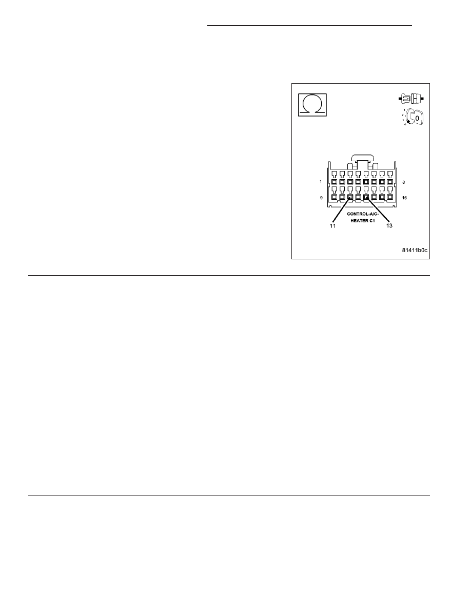
CHECK (C32) RECIRCULATION DOOR DRIVER CIRCUIT FOR A SHORT TO (C34) COMMON DOOR
DRIVER CIRCUIT

Disconnect the Recirculation Door Actuator harness connector.

Measure the resistance between the (C32) Recirculation Door Driver
circuit and the (C34) Common Door Driver circuit in the A/C Heater
Control C1 harness connector.

Is the resistance below 10k ohms?

Yes

>> Repair the (C32) Recirculation Door Driver circuit for a

short to the (C34) Common Door Driver circuit.

Perform BODY VERIFICATION TEST - VER 1. (Refer to 8
-

ELECTRICAL/ELECTRONIC

CONTROL

MODULES/

FRONT CONTROL MODULE - DIAGNOSIS AND TEST-
ING).

No

>> Replace the Recirculation Door Actuator in accordance

with the Service Information.

Perform BODY VERIFICATION TEST - VER 1. (Refer to 8
-

ELECTRICAL/ELECTRONIC

CONTROL

MODULES/

FRONT

CONTROL

MODULE

-

DIAGNOSIS

AND

TESTING).

5.

RUN THE ACTUATOR DTC DETECTION TEST

Reconnect the A/C Heater Control C1 harness connector.

Turn the ignition on.

With the scan tool, erase HVAC DTCs.

With the scan tool, select System Tests and then select Actuator DTC Detection. When the test is complete, select
View DTCs.

Does the scan tool only display: B1059–RECIRCULATION DOOR CONTROL CIRCUIT LOW?

Yes

>> Replace the A/C Heater Control in accordance with the Service Information.

Perform BODY VERIFICATION TEST - VER 1. (Refer to 8 - ELECTRICAL/ELECTRONIC CONTROL
MODULES/FRONT CONTROL MODULE - DIAGNOSIS AND TESTING).

No, Other DTC(s) Displayed

Diagnose and repair the other DTC(s). If multiple DTCs are present, beginning with the common circuit,
diagnose and repair all short high DTCs and then all short low DTCs. Refer to the Table of Contents in
this Section for a complete list of all HVAC related symptoms.

No, And No Other DTCs Displayed

Using the wiring diagram as a guide, inspect the wiring and connectors for conditions causing an inter-
mittent short. Repair as necessary.

Perform BODY VERIFICATION TEST - VER 1. (Refer to 8 - ELECTRICAL/ELECTRONIC CONTROL
MODULES/FRONT CONTROL MODULE - DIAGNOSIS AND TESTING).

24 - 86

HVAC - ELECTRICAL DIAGNOSTICS

ND

B1060–CLIMATE CONTROL MOTOR(S) COMMON 1 CONTROL CIRCUIT HIGH

ND

HVAC - ELECTRICAL DIAGNOSTICS

24 - 87

B1060–CLIMATE CONTROL MOTOR(S) COMMON 1 CONTROL CIRCUIT HIGH (CONTINUED)

For the Manual Temperature Control (MTC) circuit diagram (Refer to 24 - HEATING & AIR CONDITIONING - SCHE-
MATICS AND DIAGRAMS).

For a complete wiring diagram Refer to Section 8W.

Theory of Operation

The A/C Heater Control drives the Blend Door Actuator via the (C61) Blend Door Driver circuit and the (C34) Com-
mon Door Driver circuit. The A/C Heater Control drives the Mode Door 1 (Floor to Panel) Actuator via the (C29)
Mode Door 1 Driver circuit and the (C34) Common Door Driver circuit. The A/C Heater Control drives the Mode
Door 2 (Floor to Defrost) Actuator via the (C801) Mode Door 2 Driver circuit and the (C34) Common Door Driver
circuit. The A/C Heater Control drives the Recirculation Door Actuator via the (C32) Recirculation Door Driver circuit
and the (C34) Common Door Driver circuit. All of the door actuators share the (C34) Common Door Driver circuit.
Inside the A/C Heater Control, each door actuator has its own unique driver, but all share a single common door
driver circuit. Due to the shared circuitry similar DTCs can set at the same time for multiple actuators depending
upon the type of short, its location, and the direction the actuator is moving when the short is present.

When Monitored:
When the Actuator DTC Detection Test is executed.

Set Condition:
If the (C34) Common Door Driver circuit is shorted to voltage.

Possible Causes

(C34) COMMON DOOR DRIVER CIRCUIT SHORTED TO VOLTAGE

A/C HEATER CONTROL

Diagnostic Test

1.

CHECK (C34) COMMON DOOR DRIVER CIRCUIT FOR A SHORT TO VOLTAGE

Turn the ignition off.

Disconnect the A/C Heater Control C1 harness connector.

Turn the ignition on.

Measure the voltage of the (C34) Common Door Driver circuit.

Is the voltage above 0.2 volts?

Yes

>> Repair the (C34) Common Door Driver circuit for a short to

voltage.

Perform BODY VERIFICATION TEST - VER 1. (Refer to 8
-

ELECTRICAL/ELECTRONIC

CONTROL

MODULES/

FRONT CONTROL MODULE - DIAGNOSIS AND TEST-
ING).

No

>> Go To 2

24 - 88

HVAC - ELECTRICAL DIAGNOSTICS

ND

B1060–CLIMATE CONTROL MOTOR(S) COMMON 1 CONTROL CIRCUIT HIGH (CONTINUED)

2.

RUN THE ACTUATOR DTC DETECTION TEST

Turn the ignition off.

Reconnect the A/C Heater Control C1 harness connector.

Turn the ignition on.

With the scan tool in HVAC, select System Tests and then select Actuator DTC Detection. When the test is com-
plete, select View DTCs.

Does the scan tool only display: B1060–CLIMATE CONTROL MOTOR(S) COMMON 1 CONTROL CIRCUIT
HIGH?

Yes

>> Replace the A/C Heater Control in accordance with the Service Information.

Perform BODY VERIFICATION TEST - VER 1. (Refer to 8 - ELECTRICAL/ELECTRONIC CONTROL
MODULES/FRONT CONTROL MODULE - DIAGNOSIS AND TESTING).

No, Other DTC(s) Displayed

Diagnose and repair the other DTC(s). If multiple DTCs are present, beginning with the common circuit,
diagnose and repair all short high DTCs and then all short low DTCs. Refer to the Table of Contents in
this Section for a complete list of all HVAC related symptoms.

No, And No Other DTCs Displayed

Using the wiring diagram as a guide, inspect the wiring and connectors for conditions causing an inter-
mittent short. Repair as necessary.

Perform BODY VERIFICATION TEST - VER 1. (Refer to 8 - ELECTRICAL/ELECTRONIC CONTROL
MODULES/FRONT CONTROL MODULE - DIAGNOSIS AND TESTING).

ND

HVAC - ELECTRICAL DIAGNOSTICS

24 - 89


Content   ..  1270  1271  1272  1273   ..