Dodge Dakota (ND). Manual - part 1119


  Index      Dodge     Dodge Dakota (ND) 2005 - service repair manual 2005 year


Search            


Content   ..  1117  1118  1119  1120   ..


Dodge Dakota (ND). Manual - part 1119


C230A- NEUTRAL INDICATOR CONTROL CIRCUIT LOW (CONTINUED)

3.

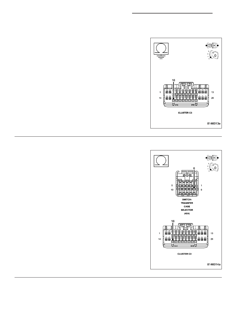
(G95) 4WD NEUTRAL INDICATOR CIRCUIT SHORTED TO GROUND

Disconnect the Transfer Case Selector Switch connector.

Measure the resistance between ground and the (G95) 4WD Neutral
Indicator circuit.

Is the resistance below 5.0 ohms?

Yes

>> Repair the (G95) 4WD Neutral Indicator circuit for a short

to ground.

Perform the TRANSFER CASE VERIFICATION TEST-
VER 1. (Refer to 8 - ELECTRICAL/ELECTRONIC CON-
TROL MODULES/TRANSFER CASE CONTROL MODULE
- DIAGNOSIS AND TESTING)

No

>> Go to 5

4.

(G95) 4WD NEUTRAL INDICATOR CIRCUIT OPEN

Disconnect the Transfer Case Selector Switch connector.

Measure the resistance of the (G95) 4WD Neutral Indicator circuit.

Is the resistance above 5.0 ohms?

Yes

>> Repair the open (G95) 4WD Neutral Indicator circuit.

Perform the TRANSFER CASE VERIFICATION TEST-
VER 1. (Refer to 8 - ELECTRICAL/ELECTRONIC CON-
TROL MODULES/TRANSFER CASE CONTROL MODULE
- DIAGNOSIS AND TESTING)

No

>> Go to 5

21 - 868

TRANSFER CASE - ELECTRICAL DIAGNOSTICS

ND

C230A- NEUTRAL INDICATOR CONTROL CIRCUIT LOW (CONTINUED)

5.

TRANSFER CASE SELECTOR SWITCH

View repair.

Repair

Replace the Transfer Case Selector Switch in accordance with the Service information.

Perform the TRANSFER CASE VERIFICATION TEST-VER 1. (Refer to 8 - ELECTRICAL/ELECTRONIC
CONTROL MODULES/TRANSFER CASE CONTROL MODULE - DIAGNOSIS AND TESTING)

6.

INSTRUMENT CLUSTER

View repair.

Repair

Replace the Instrument Cluster in accordance with the Service information.

Perform the TRANSFER CASE VERIFICATION TEST-VER 1. (Refer to 8 - ELECTRICAL/ELECTRONIC
CONTROL MODULES/TRANSFER CASE CONTROL MODULE - DIAGNOSIS AND TESTING)

7.

INTERMITTENT WIRING AND CONNECTORS

The conditions necessary to set this DTC are not present at this time.

Using the wiring diagram/schematic as a guide, inspect the wiring and connectors.

While monitoring the scan tool data relative to this circuit, wiggle test the wiring and connectors.

Look for the data to change or for the DTC to reset during the wiggle test.

Were any problems found?

Yes

>> Repair as necessary.

Perform the TRANSFER CASE VERIFICATION TEST-VER 1. (Refer to 8 - ELECTRICAL/ELECTRONIC
CONTROL MODULES/TRANSFER CASE CONTROL MODULE - DIAGNOSIS AND TESTING)

No

>> Test complete.

ND

TRANSFER CASE - ELECTRICAL DIAGNOSTICS

21 - 869

C230B- NEUTRAL INDICATOR CONTROL CIRCUIT HIGH

21 - 870

TRANSFER CASE - ELECTRICAL DIAGNOSTICS

ND

C230B- NEUTRAL INDICATOR CONTROL CIRCUIT HIGH (CONTINUED)

For a complete wiring diagram Refer to Section 8W

When Monitored:
With the ignition on.

Set Condition:
The Cluster detects high voltage on the Neutral Indicator Control Circuit.

Possible Causes

INTERMITTENT CONDITION

(G95) 4WD NEUTRAL INDICATOR CIRCUIT OPEN

(G95) 4WD NEUTRAL INDICATOR CIRCUIT SHORTED TO VOLTAGE

TRANSFER CASE SELECTOR SWIITCH

INSTRUMENT CLUSTER

Diagnostic Test

1.

DTC IS ACTIVE

Ignition on.

With the scan tool, Clear DTCs.

Shift the Transfer Case into neutral for 30 seconds in accordance with the Service Information.

With the scan tool, select View DTCs.

Does this DTC reset?

Yes

>> Go to 2

No

>> Go to 7

2.

(G95) 4WD NEUTRAL INDICATOR CIRCUIT VOLTAGE

Turn the ignition off.

Disconnect the Instrument Cluster C3 connector.

Turn the ignition on.

Measure the voltage of the (G95) 4WD Neutral Indicator circuit.

Is there any voltage present?

Yes

>> Go to 3

No

>> Go to 4

ND

TRANSFER CASE - ELECTRICAL DIAGNOSTICS

21 - 871


Content   ..  1117  1118  1119  1120   ..