Content .. 1111 1112 1113 1114 ..
Dodge Dakota (ND). Manual - part 1113
C1405- TRANSFER CASE RANGE POSITION SENSOR CIRCUIT HIGH (CONTINUED)
For a complete wiring diagram Refer to Section 8W
•
When Monitored:
Ignition on. Battery voltage between 9 and 16 volts
•
Set Condition:
FCM detects 5 volts on the Transfer Case Range Position Sensor signal circuit for 2 seconds
Possible Causes
INTERMITTENT CONDITION
(T103) 5 VOLT SUPPLY CIRCUIT SHORTED TO VOLTAGE
(D201) MODE SENSOR A CIRCUIT SHORTED TO VOLTAGE
(D201) MODE SENSOR A CIRCUIT OPEN
(G180) FCM SENSOR RETURN CIRCUIT OPEN
SHIFT MOTOR/MODE SENSOR ASSEMBLY
INTEGRATED POWER MODULE
FRONT CONTROL MODULE
Diagnostic Test
1.
T-CASE POSITION SENSOR VOLTAGE ABOVE 4.8 VOLTS
Ignition on, engine not running.
With the scan tool under Data Display, read the T-Case Position Sensor voltage.
Is the voltage above 4.8 volts?
Yes
>> Go To 2
No
>> Go to 10
2.
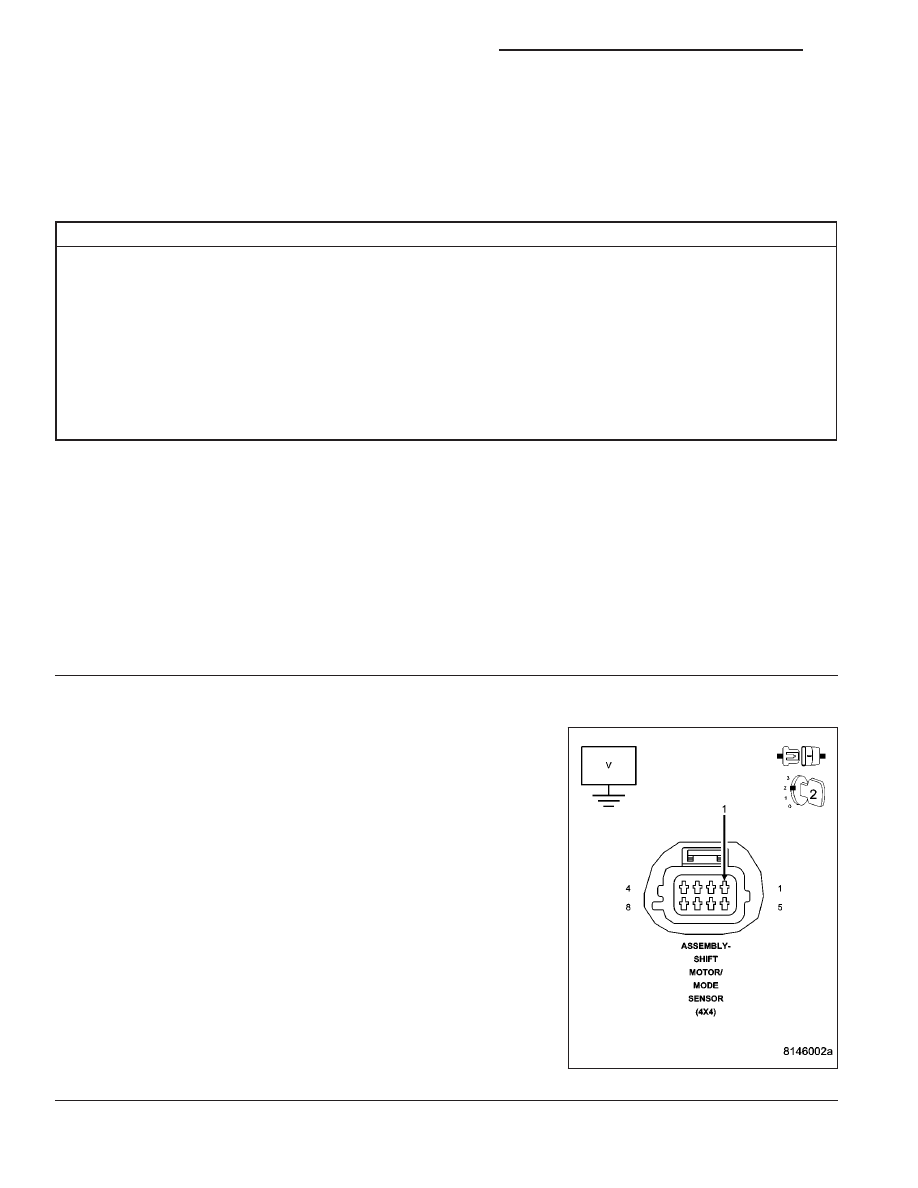
(T103) 5 VOLT SUPPLY CIRCUIT SHORTED TO VOLTAGE
Turn the ignition off.
Disconnect the Shift Motor/Mode Sensor connector.
Turn the ignition on.
Measure the voltage of the (T103) 5 Volt Supply circuit.
Is the voltage above 5.5 volts?
Yes
>> Repair the (T103) 5 Volt Supply circuit for a short to volt-
age.
Perform the TRANSFER CASE VERIFICATION TEST-
VER 1. (Refer to 8 - ELECTRICAL/ELECTRONIC CON-
TROL MODULES/TRANSFER CASE CONTROL MODULE
- DIAGNOSIS AND TESTING)
No
>> Go to 3
21 - 844
TRANSFER CASE - ELECTRICAL DIAGNOSTICS
ND