Content .. 1105 1106 1107 1108 ..
Dodge Dakota (ND). Manual - part 1107
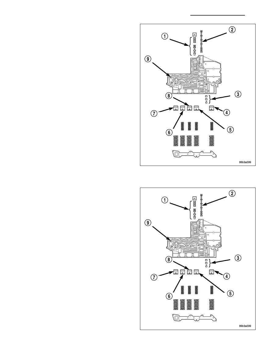
13. Remove
the
retainers
securing
the
solenoid
switch valve (1), manual valve (2), and the low/re-
verse switch valve (3) from the valve body and
remove the associated valve and spring. Tag each
valve and spring combination with location infor-
mation to aid in assembly.
CLEANING
Clean the valve housings, valves, plugs, springs, and
separator plates with a standard parts cleaning solu-
tion only. Do not use gasoline, kerosene, or any type
of caustic solution.
Do not immerse any of the electrical components in
cleaning solution. Clean the electrical components by
wiping them off with dry shop towels only.
Dry all except the electrical parts with compressed air.
Make sure all passages are clean and free from
obstructions. Do not use rags or shop towels to dry
or wipe off valve body components. Lint from
these materials can stick to valve body parts,
interfere with valve operation, and clog filters and
fluid passages.
21 - 820
AUTOMATIC TRANSMISSION 545RFE - SERVICE INFORMATION
ND