Dodge Dakota (ND). Manual - part 96
C1014-LEFT FRONT WHEEL SPEED COMPARATIVE PERFORMANCE (340) (CONTINUED)
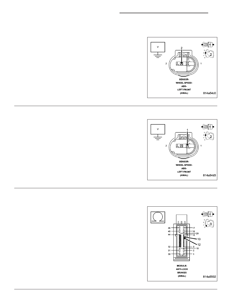
10.
(B9) LEFT FRONT WHEEL SPEED SENSOR SUPPLY CIRCUIT SHORTED TO VOLTAGE
Turn the ignition on.
Measure the voltage of the (B9) Left Front Wheel Speed Sensor Sup-
ply circuit.
Is there any voltage present?
Yes
>> Repair (B9) Left Front Wheel Speed Sensor Supply circuit
for a short to voltage.
Perform ABS VERIFICATION TEST - VER 1. (Refer to 5 -
BRAKES/ELECTRICAL - DIAGNOSIS AND TESTING)
No
>> Go To 11
11.
(B8) LEFT FRONT WHEEL SPEED SENSOR SIGNAL CIRCUIT SHORTED TO VOLTAGE
Measure the voltage of the (B8) Left Front Wheel Speed Sensor Sig-
nal circuit.
Is there any voltage present?
Yes
>> Repair the (B8) Left Front Wheel Speed Sensor Signal cir-
cuit for a short to voltage.
Perform ABS VERIFICATION TEST - VER 1. (Refer to 5 -
BRAKES/ELECTRICAL - DIAGNOSIS AND TESTING)
No
>> Go To 12
12.
(B9) LEFT FRONT WHEEL SPEED SENSOR SUPPLY CIRCUIT SHORTED TO THE (B8) LEFT FRONT
WHEEL SPEED SENSOR SIGNAL CIRCUIT
Turn the ignition off.
Measure the resistance between the (B9) Left Front Wheel Speed
Sensor Supply circuit and the (B8) Left Front Wheel Speed Sensor
Signal circuit at the Anti-lock Brake Module harness connector.
Is the resistance below 5.0 ohms?
Yes
>> Repair (B9) Left Front Wheel Speed Sensor Supply circuit
for a short to the (B8) Left Front Wheel Speed Sensor Sig-
nal circuit.
Perform ABS VERIFICATION TEST - VER 1. (Refer to 5 -
BRAKES/ELECTRICAL - DIAGNOSIS AND TESTING)
No
>> Go To 13
5 - 154
BRAKES - ABS ELECTRICAL DIAGNOSTICS
ND