Dodge Dakota (ND). Manual - part 92


  Index      Dodge     Dodge Dakota (ND) 2005 - service repair manual 2005 year


Search            


Content   ..  90  91  92  93   ..


Dodge Dakota (ND). Manual - part 92


C100A-LEFT FRONT WHEEL SPEED SENSOR CIRCUIT (340) (CONTINUED)

6.

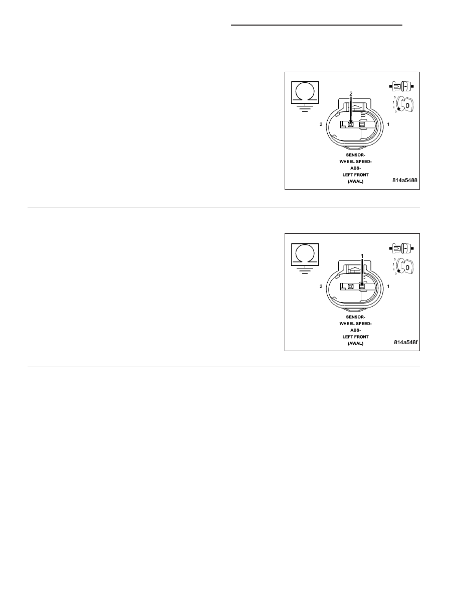
(B9) LEFT FRONT WHEEL SPEED SENSOR SUPPLY CIRCUIT SHORTED TO GROUND

Turn the ignition off.

Disconnect the Left Front Wheel Speed Sensor harness connector.

Disconnect the Anti-lock Brake Module harness connector.

NOTE: Check connector - Clean/repair as necessary.
Measure the resistance between the (B9) Left Front Wheel Speed
Sensor Supply circuit and ground.

Is the resistance above 5.0 ohms?

Yes

>> Go To 7

No

>> Repair the (B9) Left Front Wheel Speed Sensor Supply

circuit for a short to ground.

Perform ABS VERIFICATION TEST - VER 1. (Refer to 5 -
BRAKES/ELECTRICAL - DIAGNOSIS AND TESTING)

7.

(B8) LEFT FRONT WHEEL SPEED SENSOR SIGNAL CIRCUIT SHORTED TO GROUND

Measure the resistance between the (B8) Left Front Wheel Speed
Sensor Signal circuit and ground.

Is the resistance above 5.0 ohms?

Yes

>> Go To 8

No

>> Repair the (B8) Left Front Wheel Speed Sensor Signal cir-

cuit for a short to ground.

Perform ABS VERIFICATION TEST - VER 1. (Refer to 5 -
BRAKES/ELECTRICAL - DIAGNOSIS AND TESTING)

5 - 138

BRAKES - ABS ELECTRICAL DIAGNOSTICS

ND

C100A-LEFT FRONT WHEEL SPEED SENSOR CIRCUIT (340) (CONTINUED)

8.

(B9) LEFT FRONT WHEEL SPEED SENSOR SUPPLY CIRCUIT OPEN

Measure the resistance of the (B9) Left Front Wheel Speed Sensor
Supply circuit.

Is the resistance below 5 ohms?

Yes

>> Go To 9

No

>> Repair the open (B9) Left Front Wheel Speed Sensor Sup-

ply circuit.

Perform ABS VERIFICATION TEST - VER 1. (Refer to 5 -
BRAKES/ELECTRICAL - DIAGNOSIS AND TESTING)

9.

(B8) LEFT FRONT WHEEL SPEED SENSOR SIGNAL CIRCUIT OPEN

Measure the resistance of the (B8) Left Front Wheel Speed Sensor
Signal circuit.

Is the resistance below 5 ohms?

Yes

>> Go To 10

No

>> Repair the open (B8) Left Front Wheel Speed Sensor Sig-

nal circuit.

Perform ABS VERIFICATION TEST - VER 1. (Refer to 5 -
BRAKES/ELECTRICAL - DIAGNOSIS AND TESTING)

ND

BRAKES - ABS ELECTRICAL DIAGNOSTICS

5 - 139

C100A-LEFT FRONT WHEEL SPEED SENSOR CIRCUIT (340) (CONTINUED)

10.

(B9) LEFT FRONT WHEEL SPEED SENSOR SUPPLY CIRCUIT SHORTED TO VOLTAGE

Turn the ignition on.

Measure the voltage of the (B9) Left Front Wheel Speed Sensor Sup-
ply circuit.

Is there any voltage present?

Yes

>> Repair (B9) Left Front Wheel Speed Sensor Supply circuit

for a short to voltage.

Perform ABS VERIFICATION TEST - VER 1. (Refer to 5 -
BRAKES/ELECTRICAL - DIAGNOSIS AND TESTING)

No

>> Go To 11

11.

(B8) LEFT FRONT WHEEL SPEED SENSOR SIGNAL CIRCUIT SHORTED TO VOLTAGE

Measure the voltage of the (B8) Left Front Wheel Speed Sensor Sig-
nal circuit.

Is there any voltage present?

Yes

>> Repair the (B8) Left Front Wheel Speed Sensor Signal cir-

cuit for a short to voltage.

Perform ABS VERIFICATION TEST - VER 1. (Refer to 5 -
BRAKES/ELECTRICAL - DIAGNOSIS AND TESTING)

No

>> Go To 12

12.

(B9) LEFT FRONT WHEEL SPEED SENSOR SUPPLY CIRCUIT SHORTED TO THE (B8) LEFT FRONT
WHEEL SPEED SENSOR SIGNAL CIRCUIT

Turn the ignition off.

Measure the resistance between the (B9) Left Front Wheel Speed
Sensor Supply circuit and the (B8) Left Front Wheel Speed Sensor
Signal circuit at the Anti-lock Brake Module harness connector.

Is the resistance below 5.0 ohms?

Yes

>> Repair (B9) Left Front Wheel Speed Sensor Supply circuit

for a short to the (B8) Left Front Wheel Speed Sensor Sig-
nal circuit.

Perform ABS VERIFICATION TEST - VER 1. (Refer to 5 -
BRAKES/ELECTRICAL - DIAGNOSIS AND TESTING)

No

>> Go To 13

5 - 140

BRAKES - ABS ELECTRICAL DIAGNOSTICS

ND

C100A-LEFT FRONT WHEEL SPEED SENSOR CIRCUIT (340) (CONTINUED)

13.

LEFT FRONT WHEEL SPEED SENSOR

Turn the ignition off.

Connect the Left Front Wheel Speed Sensor harness connector.

Measure the resistance between the (B9) Left Front Wheel Speed
Sensor Supply circuit and (B8) Left Front Wheel Speed Sensor Signal
circuit at the Anti-lock Brake Module harness connector.

NOTE: The resistance should be approximately 1600–2300 ohms
at 76 degrees F.

Is the resistance within the noted range?

Yes

>> Go to 14

No

>> Replace the Left Front Wheel Speed Sensor in accor-

dance with the Service Information.

Perform ABS VERIFICATION TEST - VER 1. (Refer to 5 -
BRAKES/ELECTRICAL - DIAGNOSIS AND TESTING)

14.

ANTI-LOCK BRAKE MODULE

Turn the ignition off.

Inspect the related wiring harness. Look for any chafed, pierced, pinched, or partially broken wires.

Inspect the related wire harness connectors. Look for broken, bent, pushed out, or corroded terminals.

Refer to any Technical Service Bulletins that may apply.

Were any problems found?

Yes

>> Repair as necessary in accordance with the Service Information.

Perform ABS VERIFICATION TEST - VER 1. (Refer to 5 - BRAKES/ELECTRICAL - DIAGNOSIS AND
TESTING)

No

>> Replace the Anti-lock Brake Module in accordance with the Service Information.

Perform ABS VERIFICATION TEST - VER 1. (Refer to 5 - BRAKES/ELECTRICAL - DIAGNOSIS AND
TESTING)

15.

WIRING HARNESS INSPECTION

Turn the ignition off.

NOTE: Towing the vehicle with ignition ON may set this DTC.
Inspect the related wiring harness. Look for any chafed, pierced, pinched, or partially broken wires.

Inspect the related wire harness connectors. Look for broken, bent, pushed out, or corroded terminals.

Refer to any Technical Service Bulletins that may apply.

Were any problems found?

Yes

>> Repair as necessary in accordance with the Service Information.

Perform ABS VERIFICATION TEST - VER 1. (Refer to 5 - BRAKES/ELECTRICAL - DIAGNOSIS AND
TESTING)

No

>> Test Complete.

ND

BRAKES - ABS ELECTRICAL DIAGNOSTICS

5 - 141


Content   ..  90  91  92  93   ..