Chrysler Le Baron, Dodge Dynasty, Plymouth Acclaim. Manual - part 286


  Index      Dodge     Chrysler Le Baron, Dodge Dynasty, Plymouth Acclaim - service repair manual 1993 year


Search            


Content   ..  284  285  286  287   ..


Chrysler Le Baron, Dodge Dynasty, Plymouth Acclaim. Manual - part 286


ing, detonation and cooling system malfunctions also
can cause spark plug overheating.

SPARK PLUG SERVICE

When replacing the spark plug and coil cables,

route the cables correctly and secure them in the ap-
propriate retainers. Failure to route the cables prop-
erly can cause the radio to reproduce ignition noise,
cross ignition of the spark plugs or short circuit the
cables to ground.

SPARK PLUG REMOVAL

Always remove the spark plug cable by grasping at

the spark plug boot turning, the boot 1/2 turn and
pulling straight back in a steady motion.

(1) Prior to removing the spark plug spray com-

pressed air around the spark plug hole and the area
around the spark plug.

(2) Remove the spark plug using a quality socket

with a rubber or foam insert.

(3) Inspect the spark plug condition. Refer to

Spark Plug Condition in this section.

SPARK PLUG GAP ADJUSTMENT

Check the spark plug gap with a gap gauge. If the

gap is not correct, adjust it by bending the ground
electrode (Fig. 6).

SPARK PLUG INSTALLATION

(1) To avoid cross threading, start the spark plug

into the cylinder head by hand.

(2) Tighten spark plugs to 28 N

Im (20 ft. lbs.)

torque.

(3) Install spark plug cables over spark plugs.

POWERTRAIN CONTROL MODULE (PCM)

The ignition system is regulated by the powertrain

control module (PCM) (Fig. 14). The PCM supplies
battery voltage to the ignition coil through the Auto
Shutdown (ASD) Relay. The PCM also controls the
ground circuit for the ignition coil. By switching the

ground path for the coil on and off, the PCM adjusts
ignition timing to meet changing engine operating
conditions.

During the crank-start period the PCM advances

ignition timing a set amount. During engine opera-
tion, the amount of spark advance provided by the
PCM is determined by these input factors:
• coolant temperature

• engine RPM

• available manifold vacuum

The PCM also regulates the fuel injection system.

Refer to the Fuel Injection sections of Group 14.

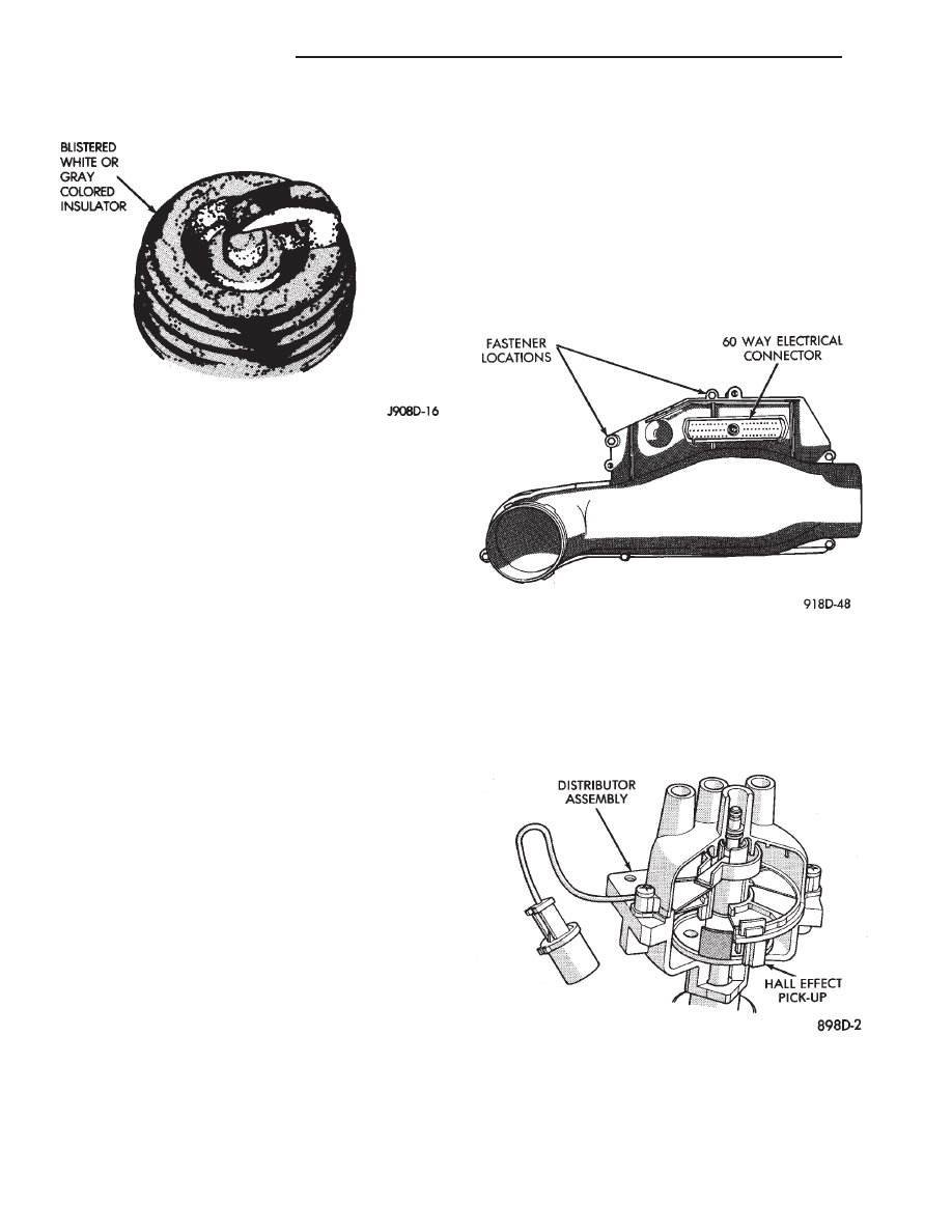
DISTRIBUTOR PICK-UP—PCM INPUT

The engine speed input is supplied to the power-

train control module (PCM) by the distributor pick-
up. The distributor pick-up is a Hall Effect device
(Fig. 15 or Fig. 16).

A shutter (sometimes referred to as an interrupter)

is attached to the distributor shaft. The shutter con-
tains four blades, one per engine cylinder. A switch
plate is mounted to the distributor housing above the
shutter. The switch plate contains the distributor

Fig. 14 Powertrain control module (PCM)

Fig. 15 Distributor—2.2L and 2.5L TBI Engines

Fig. 13 Spark Plug Overheating

8D - 6

IGNITION SYSTEMS

Ä

pick-up (a Hall Effect device and magnet) through
which the shutter blades rotate. As the shutter
blades pass through the pick-up, they interrupt the
magnetic field. The Hall effect device in the pick-up
senses the change in the magnetic field and switches
on and off (which creates pulses), generating the in-
put signal to the PCM. The PCM calculates engine
speed through the number of pulses generated.

On 2.5L MPI (flexible fuel AA-Body) engines, one

of the shutter blades has a window cut into it. The
PCM determines injector synchronization from the
window. Also, the PCM uses the input for detonation
control.

DISTRIBUTOR PICK-UP—3.0L ENGINE

The distributor pick-up provides two inputs to the

powertrain control module (PCM). From one input
the PCM determines RPM (engine speed). From the
other input it derives crankshaft position. The PCM
regulates injector synchronization and adjusts igni-
tion timing and engine speed based on these inputs.

The distributor pick-up contains two signal gener-

ators. The pick-up unit consists of 2 light emitting
diodes (LED), 2 photo diodes, and a separate timing
disk. The timing disk contains two sets of slots. Each
set of slots rotates between a light emitting diode
and a photo diode (Fig. 17). The inner set contains 6
large slots, one for each cylinder. The outer set con-
tains several smaller slots.

The outer set of slots on the rotating disk repre-

sents 2 degrees of crankshaft rotation. Up to 1200
engine RPM, the PCM uses the input from the outer
set of slots to increase ignition timing accuracy.

The outer set of slots contains a 10 degree flat spot.

This area is not slotted (Fig. 17). The flat spot tells
the PCM that the next piston at TDC will be number
6. Each piston’s position is referenced by one of the
six inner slots (Fig. 18).

As each slot on the timing disk passes between the

diodes, they interrupt the beam from the light emit-
ting diode. This creates an alternating voltage in
each photo diode which is converted into on-off
pulses. The pulses are the input to the PCM.

During cranking, the PCM cannot determine which

cylinder will be at TDC until the 10 degree flat spot
on the outer set of slots rotates through the optical
unit. Once the flat spot is detected, the PCM knows
piston number 6 will be the next piston at TDC.

Since the disk rotates at half crankshaft speed, it

may take up to 2 engine revolutions during cranking
before the PCM determines the position of piston
number 6. For this reason the PCM energizes all six
injectors at the same time until it senses the position
of piston number 6.

COOLANT TEMPERATURE SENSOR

On 2.2L TBI, 2.5L TBI and 2.5L MPI engines, the

coolant temperature sensor is installed behind the
thermostat housing and ignition coil in the hot box
(Fig. 19). On 3.0L engines the sensor is located next

Fig. 16 Distributor—2.5L MPI (Flexible Fuel

AA-Body)

Fig. 17 Distributor Pick-up—3.0L Engine

Fig. 18 Inner and Outer Slots of Rotating Disk—3.0L

Engine

Ä

IGNITION SYSTEMS

8D - 7

to the thermostat housing (Fig. 20). The sensor pro-
vides an input voltage to the powertrain control mod-
ule (PCM). The sensor is a variable resistance
(thermistor) with a range of -40°F to 265°F. As cool-
ant

temperature

varies,

the

sensors

resistance

changes, resulting in a different input voltage to the
PCM.

The PCM contains different spark advance sched-

ules for cold and warm engine operation. The sched-
ules

reduce

engine

emissions

and

improve

driveability. Because spark advance changes at dif-
ferent engine operating temperatures during warm-
up, all spark advance testing should be done with the
engine fully warmed.

The PCM demands slightly richer air-fuel mixtures

and higher idle speeds until the engine reaches nor-
mal operating temperature.

The coolant sensor input is also used for radiator

fan control.

MANIFOLD ABSOLUTE PRESSURE (MAP) SENSOR

The MAP sensor reacts to absolute pressure in the

intake manifold and provides an input voltage to the
powertrain control module (PCM). As engine load
changes, manifold pressure varies. The changes in
engine load causes the MAP sensors output voltage
to change. The change in MAP sensor output voltage
results in a different input voltage to the PCM.

The input voltage level supplies the PCM with in-

formation relating to ambient barometric pressure
during engine start-up (cranking) and engine load
while its operating. The PCM uses this input along
with inputs from other sensors to adjust air-fuel mix-
ture.

On 2.2L TBI, 2.5L TBI and 2.5L MPI (flexible fuel

AA-body) engines, the MAP sensor is mounted to the
dash panel (Fig. 21 or Fig. 22). On 3.0L engines, the
sensor is mounted to a bracket across from the dis-
tributor (Fig. 23). The sensor is connected to the
throttle body or intake manifold with a vacuum hose
and to the PCM electrically.

AUTO SHUTDOWN (ASD) RELAY AND FUEL PUMP
RELAY

The powertrain control module (PCM) operates the

auto shutdown (ASD) relay and fuel pump relay
through one ground path. The PCM operates the re-
lays by switching the ground path on and off. Both
relays turn on and off at the same time.

The ASD relay connects battery voltage to the fuel

injector and ignition coil. The fuel pump relay con-
nects battery voltage to the fuel pump and oxygen
sensor heating element.

The PCM turns the ground path off when the igni-

tion switch is in the Off position. Both relays are off.
When the ignition switch is in the On or Crank po-
sition, the PCM monitors the distributor pick-up sig-

Fig. 19 Coolant Temperature Sensor—2.2L TBI, 2.5L

TBI and 2.5L MPI Engines

Fig. 20 Coolant Temperature Sensor—3.0L Engines

Fig. 21 MAP Sensor—2.2L and 2.5L TBI Engines

8D - 8

IGNITION SYSTEMS

Ä

nal. From the pick-up signal, the PCM determines
engine speed and ignition timing (coil dwell). If the
PCM does not receive a distributor signal when the
ignition switch is in the Run position, it will de-en-
ergize both relays. When the relays are de-energized,
battery voltage is not supplied to the fuel injector, ig-
nition coil, fuel pump and oxygen sensor heating el-
ement.

On AC, AG, AJ and AY models, the ASD relay and

fuel pump relay are located in the power distribution
center (Fig. 24, 25, 26, or 27).

On AA and AP models, the ASD relay and fuel

pump relay are mounted on the drivers side fender
well, next to the strut tower (Fig. 28).

IGNITION COIL

The 2.2L TBI, 2.5L TBI, 2.5L MPI and 3.0L en-

gines use an epoxy type coil. The coils are not oil
filled. The windings are embedded in a heat and vi-
bration resistant epoxy compound.

The powertrain control module (PCM) operates the

ignition coil through the auto shutdown (ASD) relay.

When the relay is energized by the PCM, battery
voltage is connected to the ignition coil positive ter-
minal. The PCM will de-energize the ASD relay if it
does not receive an input from the distributor pick-

Fig. 22 MAP Sensor—2.5L MPI (Flexible Fuel

AA-Body) Engines

Fig. 23 MAP Sensor—3.0L Engine

Fig. 24 Power Distribution Center (PDC) (AC Body)

Fig. 25 Relay Identification (AC Body)

Fig. 26 Power Distribution Center (PDC) (AG and AJ

Body)

Ä

IGNITION SYSTEMS

8D - 9


Content   ..  284  285  286  287   ..