Chrysler Le Baron, Dodge Dynasty, Plymouth Acclaim. Manual - part 248
HYDRAULIC SYSTEM CONTROL VALVES
INDEX
page
page
General Information
. . . . . . . . . . . . . . . . . . . . . . . 10
Hydraulic System Service Procedures
. . . . . . . . . 11
Pressure Differential Warning Light Switch
. . . . . . 10
GENERAL INFORMATION
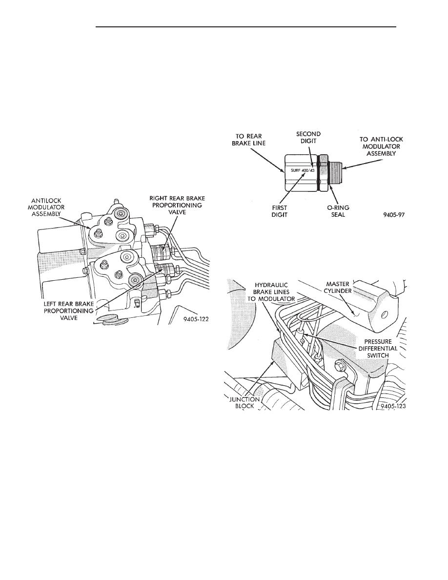
All models equipped with a Bendix Antilock 4 Brake
System have 2 screw-in type proportioning valves.
There is 1 valve for each individual rear wheel hydrau-
lic brake line. The proportioning valves are mounted
directly into the rear brake outlet ports of the modula-
tor assembly (Fig. 1).
The proportioning valves limit brake pressure to the
rear brakes after a certain pressure (split point) is
reached. This improves front to rear brake balance
during normal braking.
Screw-in proportioning valves can be identified by
numbers stamped on the body of the valve. The first
digit represents the slope, the second digit represents
the split (cut-in) point, and the arrow represents the
flow direction of the valve. Be sure numbers listed
on a replacement valve are the same as on the
valve that is being removed. See (Fig. 2) for detail of
the valve identification.
PRESSURE DIFFERENTIAL WARNING LIGHT
SWITCH
The hydraulic brake system, on vehicles equipped
with the Bendix Antilock 4 Brake System is split
diagonally. The left front and right rear brakes are on
one hydraulic system, and the right front and left
rear are on another. Both systems are routed
through, and hydraulically separated by the Pressure
Differential Switch (Fig. 3) mounted in the hydraulic
brake tube junction block. The function of the Pressure
Differential Switch is to alert the driver of a malfunc-
tion in the brake hydraulic system.
If hydraulic pressure is lost in one system, the
warning light switch will activate the RED brake
warning light on the instrument panel, when the brake
pedal is depressed. At this point the brakes hydraulic
system requires immediate service. However, since the
brake systems are split diagonally the vehicle will
retain 50% of its stopping capability in the event of a
failure in either half.
The warning light switch is the latching type. It
will automatically center itself after the repair is
made and the brake pedal is depressed.
Fig. 1 Rear Brake Proportioning Valve Location On
Modulator Assembly
Fig. 2 ABS PROPORTIONING VALVE IDENTIFICA-
TION
Fig. 3 Pressure Differential Warning Light Switch In
Junction Block.
5 - 10
BRAKES
Ä