Chrysler Le Baron, Dodge Dynasty, Plymouth Acclaim. Manual - part 234
WARNING: FAILURE TO DE-PRESSURIZE THE AC-
CUMULATOR PRIOR TO PERFORMING THIS OPER-
ATION
MAY
RESULT
IN
PERSONAL
INJURY
AND/OR DAMAGE TO PAINTED SURFACES.
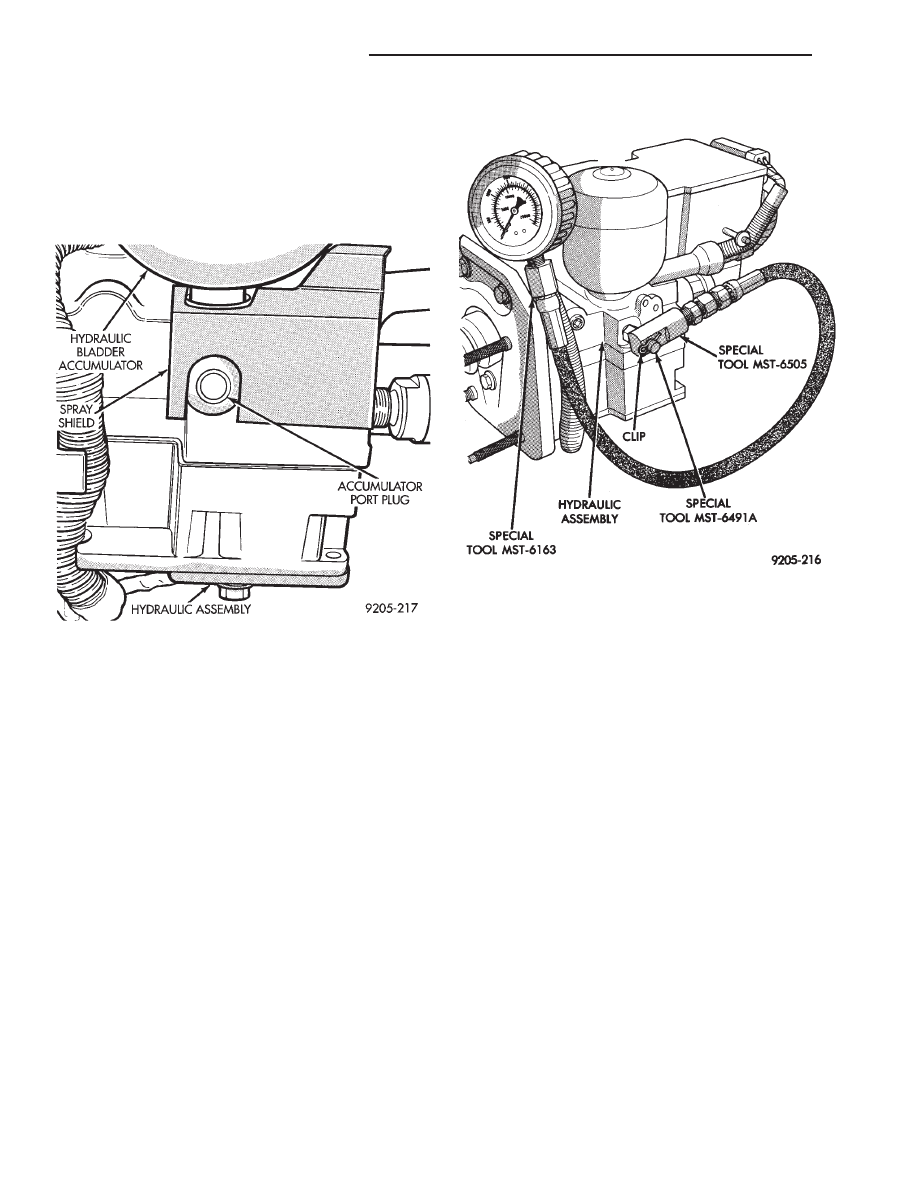
(2) Remove hydraulic assembly accumulator port
plug,located on right hand side of hydraulic assembly
(Fig. 1).
(3) Install pressure gauge to hydraulic assembly
adaptor into accumulator port of hydraulic assembly
(Fig. 2). Then torque adaptor to 10 N
Im (7.5 ft. lbs.).
(4) Install adaptor onto the pressure gauge hose
(Fig. 2) and tighten the fitting to 15 N
Im (11 ft. lbs.)
torque.
(5) Install pressure gauge and hose adaptor assem-
bly onto the adaptor installed in the hydraulic as-
sembly accumulator port. Then install the retaining
clip into the grove on the accumulator port adaptor
(Fig. 2). MAKE SURE THAT THE RETAINING
CLIP IS INSTALLED ON THE ACCUMULATOR
PORT ADAPTOR BEFORE RE-PRESSURIZING
THE HYDRAULIC SYSTEM.
WARNING:
BEFORE
REMOVING
PRESSURE
GAUGE AND ADAPTOR, BE SURE TO DE-PRES-
SURIZE THE HYDRAULIC ASSEMBLY. THEN IN-
STALL AND TIGHTEN ACCUMULATOR PORT PLUG
TO 12 N
I
M (9 FT. LBS.).
It is not necessary to bleed the hydraulic assembly
or brake system after installation and removal of the
pressure gauge. Unless additional tubes, hoses, or fit-
tings were removed or loosened.
HYDRAULIC ASSEMBLY INTERNAL LEAK
CHECK
If an internal leak is suspected in the ABS hydrau-
lic circuit, Test Gauge, Special Tool 6685 has been
developed to assist in the diagnostics. This fixture
will assist in determining if there is an internal leak;
and if the leak is in the hydraulic unit or the pump
motor assembly. It can be used whether the pump
shuts off or not.
Test Gauge, Special Tool 6685 installation and op-
eration procedure is detailed below. Refer to the Hy-
draulic Pressure Performance Test in the 1993
Bendix Anti-Lock 10 Diagnostic Manual for the re-
quired test procedures.
WARNING: FAILURE TO DE-PRESSURIZE THE AC-
CUMULATOR PRIOR TO PERFORMING THIS OPER-
ATION
MAY
RESULT
IN
PERSONAL
INJURY
AND/OR DAMAGE TO PAINTED SURFACES.
(1) De-pressurize the accumulator by pumping the
brake pedal a minimum of 40 times with the ignition
off. The procedure is fully explained under De-Pres-
surizing Hydraulic Accumulator which is described
earlier in this System Diagnosis Section.
(2) Remove wiring harness connector from dual
function pressure switch on bottom of hydraulic as-
sembly. Connect wiring harness from Test Gauge,
Special Tool 6685 into wiring harness connector re-
moved from dual function pressure switch.
Fig. 1 Hydraulic Assembly Accumulator Port Plug
Location
Fig. 2 Pressure Gauge and Adapter Installed on
Hydraulic Assembly
5 - 90
ANTI-LOCK 10 BRAKE SYSTEM
Ä