Chrysler Le Baron, Dodge Dynasty, Plymouth Acclaim. Manual - part 212


  Index      Dodge     Chrysler Le Baron, Dodge Dynasty, Plymouth Acclaim - service repair manual 1993 year


Search            


Content   ..  210  211  212  213   ..


Chrysler Le Baron, Dodge Dynasty, Plymouth Acclaim. Manual - part 212


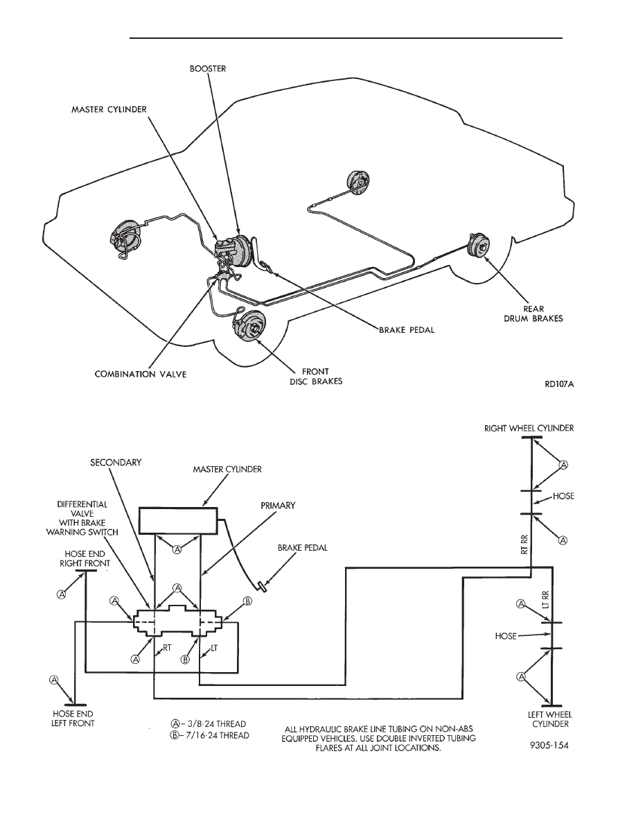
Fig. 1 Diagonally Split Braking System (Typical Non-ABS System)

Fig. 2 Proper Nut Thread Size And Tube Routing (Non-ABS Equipped)

5 - 2

BRAKES

Ä

Fig. 3 Proper Nut Thread Size And Tube Routing (AC & AY Body With ABS)

Fig. 4 Proper Nut Thread Size And Tube Routing (AG AJ AP AA Body) W/ABS)

Ä

BRAKES

5 - 3

SERVICE ADJUSTMENTS

INDEX

page

page

Adjusting Rear Service Brakes

. . . . . . . . . . . . . . . 4

Bleeding Brake System

. . . . . . . . . . . . . . . . . . . . . 6

Brake Hose and Tubing

. . . . . . . . . . . . . . . . . . . 11

Master Cylinder Fluid Level

. . . . . . . . . . . . . . . . . . 4

Stop Lamp Switch Adjustment (All Vehicles)

. . . . 13

Test for Fluid Contamination

. . . . . . . . . . . . . . . . . 7

Testing Application Adjuster Operation

. . . . . . . . . 6

Wheel Stud Nut Tightening

. . . . . . . . . . . . . . . . . . 7

MASTER CYLINDER FLUID LEVEL

ALL EXCEPT AC/AY BODY WITH ABS

Check master cylinder reservoir brake fluid level a

minimum of twice a year.

Master cylinder reservoirs are marked with the

words fill to bottom of rings indicating proper fluid
level (Fig. 1).

If necessary, add fluid to bring the level to the bot-

tom of the primary reservoir split ring.

Use only Mopar

t brake fluid or an equivalent from

a sealed container. Brake fluid must conform to DOT
3, specifications.

DO NOT use brake fluid with a lower boiling

point, as brake failure could result during prolonged
hard braking.

Use only brake fluid that was stored in a tightly-

sealed container.

DO NOT use petroleum-based fluid because seal

damage in the brake system will result.

AC AND AY BODY WITH ANTI-LOCK BRAKES

The hydraulic assembly is equipped with a plastic

fluid reservoir with a filter/strainer in the filler neck
of the reservoir.

The Anti-Lock brake system requires that the hy-

draulic

accumulator

be

de-pressurized

whenever

checking the brake fluid level. To check the brake
fluid level, the following procedure should be used:

(1) With the ignition switch turned to the off position

and key removed. De-pressurize hydraulic accumula-
tor by applying brake pedal approximately 40 times,
using a pedal force of approximately 220 N (50 lbs.). A
noticeable change in pedal feel will occur when accu-
mulator is de-pressurized. Continue to apply brake
pedal several times after this change in pedal feel
occurs to insure that brake system is fully de-
pressurized.

(2) Thoroughly clean both reservoir caps and sur-

rounding area of reservoir, (Fig. 2) before removing
caps. This is to avoid getting dirt into the reservoir and
contaminating the brake fluid.

(3) Inspect the brake fluid to see if it is at the proper

level, see instructions on top of reservoir. (FILL TO
TOP

OF

WHITE

SCREEN

ON

FRONT

FILTER/STRAINER.)

(4) Fill reservoir with brake fluid to top of screen

(Fig. 3) on the filter/strainer located in brake fluid
reservoir. Only use brake fluid conforming to DOT 3
specifications such as Mopar

t or equivalent.

(5) Replace brake fluid reservoir caps.

ADJUSTING REAR SERVICE BRAKES

Normally, self adjusting drum brakes will not

require manual brake shoe adjustment. Al-
though in the event of a brake reline it is advis-
able to make the initial adjustment manually to
speed up the adjusting time.

(1) Raise the vehicle so all wheels are free to turn.

See Hoisting Recommendations in the Lubrication And
Maintenance Section, at the front of this service
manual.

(2) Remove rear brake adjusting hole rubber plug

(Fig. 4), from the rear brake shoe support plate.

(3) Be sure parking brake lever is fully re-

leased. Then back off parking brake cable adjust-
ment so there is slack in the cable.

(4) Insert Brake Adjuster, Special Tool C-3784, (Fig.

5) or equivalent through the adjusting hole in support
plate and against star wheel of adjusting screw. Move
handle of tool upward until a slight drag is felt when
the road wheel is rotated.

(5) Insert a thin screwdriver or piece of welding rod

into brake adjusting hole (Fig. 5). Push adjusting lever
out

of

engagement

with

star

wheel.

Care

Fig. 1 Master Cylinder Fluid Level (All Except AC/AY

Body W/ABS)

5 - 4

BRAKES

Ä

should be taken so as not to bend adjusting lever
or distort lever spring. 
While holding adjusting
lever out of engagement with star wheel, back off star
wheel to ensure a free wheel with no brake shoe drag.

(6) Repeat above adjustment at the other rear wheel.

Install adjusting hole rubber plugs (Fig. 4) in rear
brake supports.

(7) Adjust parking brake after wheel brake adjust-

ment. See parking brake adjustment, under Parking
Brakes in this group of the service manual.

It is important to follow the above sequence to

avoid the possibility of the parking brake system
causing brake drag. This could occur if the park-
ing brakes are adjusted before the service
brakes.

Fig. 4 Brake Adjusting Hole Plug

Fig. 2 Master Cylinder Fluid Level (W/ABS)

Fig. 3 ABS Reservoir Fill Level On Filter/Strainer

Ä

BRAKES

5 - 5


Content   ..  210  211  212  213   ..