Chrysler Le Baron, Dodge Dynasty, Plymouth Acclaim. Manual - part 147


  Index      Dodge     Chrysler Le Baron, Dodge Dynasty, Plymouth Acclaim - service repair manual 1993 year


Search            


Content   ..  145  146  147  148   ..


Chrysler Le Baron, Dodge Dynasty, Plymouth Acclaim. Manual - part 147


WHEELS SERVICE PROCEDURES

INDEX

page

page

General Information

. . . . . . . . . . . . . . . . . . . . . . . . 6

Tire and Wheel Balance

. . . . . . . . . . . . . . . . . . . . 6

Tire and Wheel Run Out

. . . . . . . . . . . . . . . . . . . . 7

Wheel Installation

. . . . . . . . . . . . . . . . . . . . . . . . . 6

Wheel Replacement

. . . . . . . . . . . . . . . . . . . . . . . 6

GENERAL INFORMATION

Original equipment wheels are designed for proper

operation at all loads up to the maximum vehicle ca-
pacity.

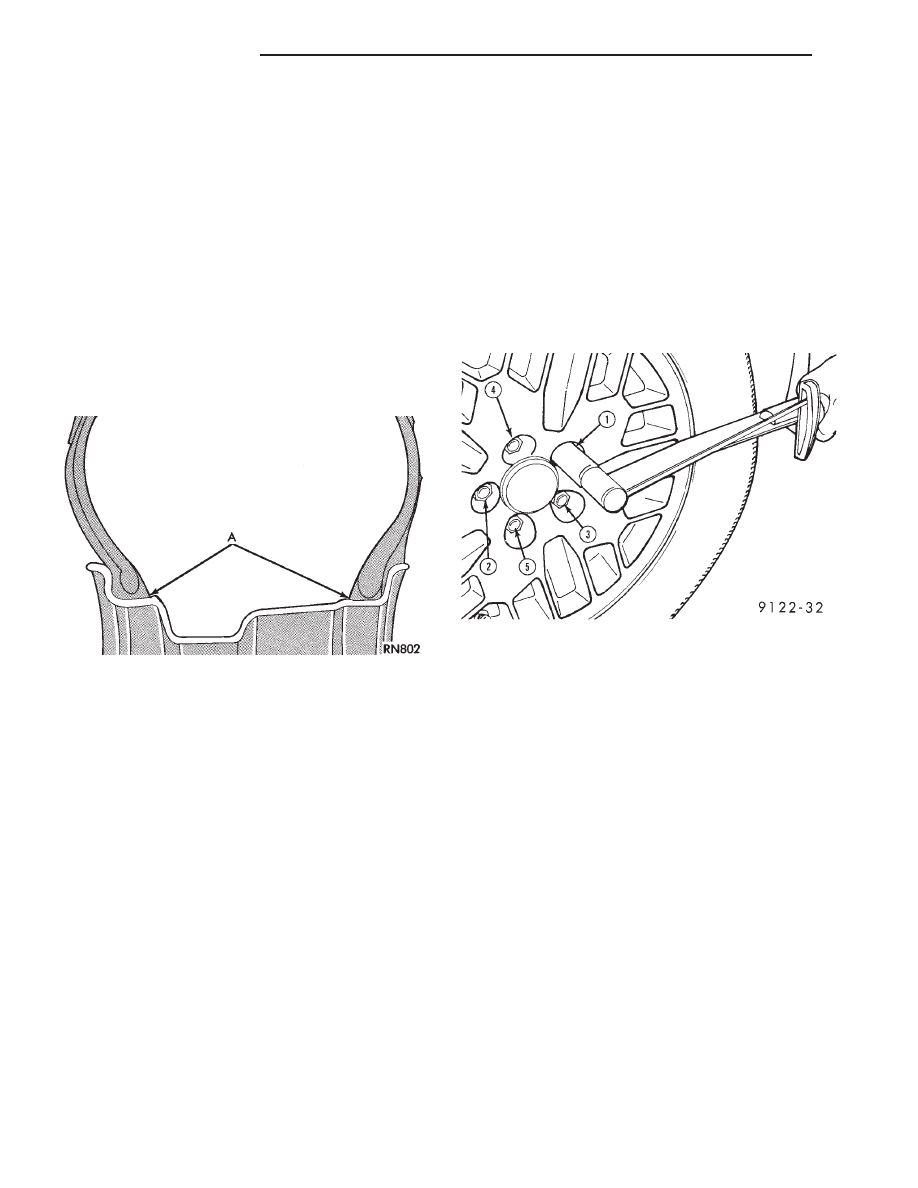
All models use steel or cast aluminum drop center

wheels. The safety rim wheel (Fig. 1) has raised sec-
tions between the rim flanges and the rim well A.

Initial inflation of the tires forces the bead over

these raised sections. In case of tire failure the raised
sections help hold the tire in position on the wheel
until the vehicle can be brought to a safe stop.

Cast aluminum wheels require special balance

weights and alignment equipment.

WHEEL INSTALLATION

The wheel studs and nuts are designed for specific

applications and must be replaced with equivalent
parts. Do not use replacement parts of lessor quality
or a substitute design. All aluminum and some steel
wheels have wheel stud nuts which feature an en-
larged nose. This enlarged nose is necessary to en-
sure proper retention of the aluminum wheels.

Before installing the wheel, be sure to remove any

build up of corrosion on the wheel mounting surfaces
with scraping and wire brushing. Installing wheels
without good metal-to-metal contact could cause later
loosening of wheel nuts. This could adversely affect
the safety and handling of your vehicle.

To install the wheel, position it properly on the

mounting surface using the hub pilot as a guide. All

wheel nuts should be lightly tightened before progres-
sively tightening them in sequence (Fig. 2). Tighten
wheel nuts to 129 N

Im (95 ft. lbs.). Never use oil or

grease on studs or nuts.

WHEEL REPLACEMENT

Wheels must be replaced if they:

• have excessive run out

• are bent or dented

• leak air through welds

• have damaged bolt holes

Wheel repairs employing hammering, heating, or

welding are not allowed.

Original equipment replacement wheels are avail-

able through your dealer. When obtaining wheels from
any other source, the replacement wheels should be
equivalent in load carrying capacity. The wheel dimen-
sions (diameter, width, offset, and mounting configura-
tion) must match original equipment wheels. Failure to
use equivalent replacement wheels may adversely af-
fect the safety and handling of your vehicle. Replace-
ment with used wheels is not recommended as
their service history may have included severe
treatment or very high mileage and they could
fail without warning.

TIRE AND WHEEL BALANCE

Balancing need is indicated by vibration of seats,

floor pan, or steering wheel when driving over 90 km/h
(55 mph) on a smooth road.

Fig. 1 Safety Rim

Fig. 2 Tightening Wheel Nuts (5-Stud)

22 - 6

WHEELS—TIRES

Ä

It is recommended that a two plane dynamic bal-

ancing machine be used when a wheel and tire as-
sembly require balancing. Static balancing should be
used only when a two plane dynamic balancing is not
available.

For static imbalance, find location of heavy spot

causing imbalance and counterbalance wheel directly
opposite the heavy spot. Determine weight required
to counterbalance the area of imbalance. Place half
of this weight on the inner rim flange. Then place
the other half on the outer rim flange (Fig. 3). Off-
vehicle balancing is preferred.

TIRE AND WHEEL RUN OUT

Radial run out is the difference between the high

and low points on the tire or wheel periphery.

Lateral run out is the wobble of the tire or wheel.
Radial run out of more than 1.5 mm (.060 inch)

measured at the center line of the tread may cause
the vehicle to shake.

Lateral run out of more than 2.0 mm (.080 inch)

measured near the shoulder of the tire may cause the
vehicle to shake.

Sometimes radial run out can be reduced by relo-

cating the wheel and tire assembly on the mounting
studs (See Method 1). If this does not reduce run out
to an acceptable level, the tire can be rotated on the
wheel. (See Method 2).

METHOD 1 (RELOCATE WHEEL ON HUB)

Check accuracy of the wheel mounting surface;ad-

just wheel bearings.

Drive vehicle a short distance to eliminate tire flat

spotting from a parked position.

Make sure all wheel nuts are properly torqued

(Fig. 2).

Use run out gauge D-128-TR to determine run out

(Fig. 4).

Relocate wheel on the mounting, two studs over

from the original position.

Retighten wheel nuts (Fig. 2) until all are properly

torqued, to eliminate brake distortion.

Check radial run out. If still excessive, mark tire

sidewall, wheel, and stud at point of maximum run
out (Fig. 5), and proceed to Method #2.

METHOD 2 (RELOCATE TIRE ON WHEEL)

Rotating tire on wheel is particularly effective

when there is run out in both tire and wheel.

Remove tire from wheel and remount wheel on hub

in former position.

Check wheel radial run out (Fig. 6). It should be no

more than 0.9 mm (.035 inch).

Lateral run out (Fig. 6) should be no more than 1.1

mm (.045 inch).

If point of greatest wheel radial run out is near

original chalk mark, remount tire 180 degrees from
its original position. Recheck run out.

Fig. 3 Counterbalancing

Fig. 4 Run out Gauge D-128-TR

Fig. 5 Chalk Marking on Wheel, Tire, and Stud

Ä

WHEELS—TIRES

22 - 7

SPECIFICATIONS

Fig. 6 Checking Wheel Run out

TIRE SPECIFICATIONS

TORQUE SPECIFICATIONS

22 - 8

WHEELS—TIRES

Ä

BODY

CONTENTS

page

page

AA-VEHICLE BODY COMPONENT SERVICE

. . . 11

AC-VEHICLE BODY COMPONENT SERVICE

. . . 37

AG-VEHICLE BODY COMPONENT SERVICE

. . . 52

AJ-VEHICLE BODY COMPONENT SERVICE

. . . 71

AJ/27-VEHICLE CONVERTIBLE BODY

COMPONENT SERVICE

. . . . . . . . . . . . . . . . . 86

AP-VEHICLE BODY COMPONENT SERVICE

. . . 97

AP/17-VEHICLE CONVERTIBLE BODY

COMPONENT SERVICE . . . . . . . . . . . . . . . . . 117

AY-VEHICLE BODY COMPONENT SERVICE

. . 133

BODY DIAGNOSTIC PROCEDURES

. . . . . . . . . . 2

GENERAL SERVICE INFORMATION

. . . . . . . . . . 1

PAINT

. . . . . . . . . . . . . . . . . . . . . . . . . . . . . . . . . 4

POWER SUNROOF

. . . . . . . . . . . . . . . . . . . . . . . 6

WINDSHIELD

. . . . . . . . . . . . . . . . . . . . . . . . . . . 9

GENERAL SERVICE INFORMATION

VEHICLE IDENTIFICATION

Throughout this group, references to the Chrysler

Corporation vehicle family identification code is used
when describing a procedure that is unique to that
vehicle. Refer to Introduction Group of this manual for
detailed information on vehicle identification. If a
procedure is common to all vehicles covered in this
manual, no reference will be made to a vehicle family
code.

SAFETY PRECAUTIONS AND WARNINGS

WARNING: WHEN SERVICING A VEHICLE EQUIPPED
WITH AIRBAG RESTRAINT SYSTEM, REVIEW ALL
PRECAUTIONS IN GROUP 8M, RESTRAINT SYS-
TEMS. PERSONAL INJURY CAN RESULT.

EYE PROTECTION SHOULD BE USED WHEN SER-

VICING GLASS COMPONENTS. PERSONAL INJURY
CAN RESULT.

USE A BREATHING FILTER WHEN SPRAYING

PAINT OR SOLVENTS IN A CONFINED AREA. PER-
SONAL INJURY CAN RESULT.

AVOID PROLONGED SKIN CONTACT WITH PETRO-

LEUM OR ALCOHOL BASED CLEANING SOLVENTS.
PERSONAL INJURY CAN RESULT.

DO NOT VENTURE UNDER A HOISTED VEHICLE

THAT IS NOT PROPERLY SUPPORTED ON SAFETY
STANDS. PERSONAL INJURY CAN RESULT.

CAUTION: When holes must be drilled or punched in
a inner body panel, verify depth of space to the outer
body panel, electrical wiring, or other components.
Damage to vehicle can result.

Do not use abrasive chemicals or compounds on

painted surfaces. Damage to finish can result.

Do not use harsh alkaline based cleaning solvents

on painted or upholstered surfaces. Damage to finish
or color can result.

Do not hammer or pound on plastic trim panel

attaching fasteners when servicing interior trim. Plas-
tic panel can break.

Chrysler Corporation uses many different types of

push-in fasteners to secure the interior and exterior
trim to the body . Most of these fasteners can be reused
to assemble the trim during various repair procedures.
At times a push-in fastener cannot be removed without
damaging the fastener or the component it is holding.
If it is not possible to remove a fastener without
damaging a component or body, cut or brake the
fastener and use a new one when installing the com-
ponent. Never pry or pound on a plastic or press-board
trim component. Using a suitable fork-type prying
device, pry the fastener from the retaining hole behind
the component being removed. When installing, verify
that fastener is aligned with the retaining hole, by
hand, push directly on or over the fastener until it
seats. Apply a low force pull to the panel to verify that
it is secure.

When it is necessary to remove components to service

another, it should not be necessary to apply excessive
force or bend a component to remove it. Before damag-
ing a component to be reused, verify there is no hidden
fasteners or captured edges holding the component in.
Often a fastener is hidden by carpeting nap or trim
plugs.

Ä

BODY

23 - 1


Content   ..  145  146  147  148   ..