Chrysler Le Baron, Dodge Dynasty, Plymouth Acclaim. Manual - part 91


  Index      Dodge     Chrysler Le Baron, Dodge Dynasty, Plymouth Acclaim - service repair manual 1993 year


Search            


Content   ..  89  90  91  92   ..


Chrysler Le Baron, Dodge Dynasty, Plymouth Acclaim. Manual - part 91


• Air pressure leaks down below 621 kPa (90 psi),
before it remains steady.
• Output pressure builds up to less than 758 kPa
(110 psi) when it stabilizes.

If the compressor is allowed to run during this test

until it reaches its maximum output pressure of 1516
kPa (220 psi). The solenoid exhaust valve will act as

a pressure relief valve. The resulting leak-down, af-
ter the compressor is shut off, will indicate a false
leak.

SERVICE PROCEDURES

COMPRESSOR ASSEMBLY

REMOVAL

(1) Disconnect negative battery cable.
(2) Raise vehicle, see Hoisting, Group 0.
(3) Remove cover from compressor assembly. Re-

move air hose and electrical connectors (Figs. 1 and
2).

(4) Remove compressor assembly mounting bolts

and lower assembly from vehicle.

(5) Remove

mounting

bracket

bolts

and

slide

mounting bracket away from compressor.

INSTALLATION

(1) Slide mounting bracket on compressor and in-

stall bolts and tighten to 8 N

Im (70 in. lbs.) torque.

(2) Install compressor assembly to frame rail and

tighten bolts to 8 N

Im (70 in. lbs.) torque.

(3) Connect air hose and electrical connector to

compressor assembly.

(4) Install

cover

on

compressor

assembly

and

tighten bolts to 8 N

Im (70 in. lbs.) torque.

(5) Lower vehicle and connect negative battery ca-

ble.

(6) Check operation of the system.

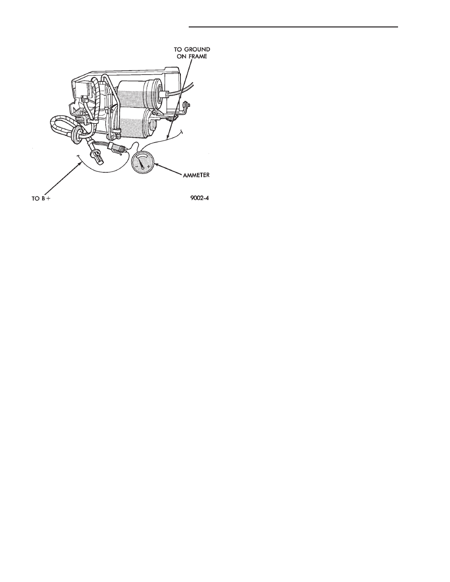
Fig. 6 Compressor Current Draw Test

2 - 62

SUSPENSION AND DRIVESHAFTS

Ä

AUTOMATIC AIR LOAD LEVELING SYSTEM WIRING SCHEMATIC

Ä

SUSPENSION AND DRIVESHAFTS

2 - 63

AUTOMATIC AIR LOAD LEVELING SYSTEM WIRING SCHEMATIC

2 - 64

SUSPENSION AND DRIVESHAFTS

Ä

REAR LEVELING DIAGNOSTIC PROCEDURES

SELF-DIAGNOSTICS

A self-diagnostic procedure is available for the ser-

vice technician to use to detect system malfunctions.

BEFORE DIAGNOSTICS TEST

Check the 20 amp fuse (position W40) and the 30

amp circuit breaker (position W5) to be assured they
are functional components.

Check all connectors that link the system into the

main body wiring harness. These include compressor,
height sensor, control module, (Fig. 7) and relay.
Also check the underbody to in trunk and leveling
harness to main body harness connectors. Also, check
all air lines, connectors, and other components for
correct installation.

TEST LAMP PIN OPERATION

The monitor lamp pin output will be activated (test

lamp on) if the detection of abnormal system opera-
tion is determined by the CM.

AFTER COMPLETION OF REPAIRS

To initiate diagnostics, disconnect the test ground

wire then reconnect for repair verification.

TERMINATION OF SELF-DIAGNOSTICS

The self-diagnostic operation is terminated when

any of the following takes place:
• Disconnecting the diagnostic input from the
ground circuit.
• Turn the ignition switch to the off position.

When the self-diagnostic operation is terminated.

The control module resumes normal operation unless
it ceases operation. Due to it detecting a system mal-
function.

TEST WEIGHT

Weight between 275-300 lbs. must be added to rear

of vehicle before diagnostic testing begins.

DIAGNOSTICS (TO START PROCESS)

(1) Remove protective connector cover from diag-

nostic connector.

(2) Insert wire into diagnostic ground pin. Then at-

tach to compressor ground pin, or as an alternate, in-
sert wire into diagnostic ground pin. Then ground
other end of test wire to body structure or a control
module fastener.

IGNITION

The following self diagnostic operation is initiated

by connecting the diagnostic ground pin to ground af-
ter ignition switch is turned ON. A monitor lamp
must be connected between the Test Lamp Ground
Pin and the Test Lamp Feed Pin to display the con-
trol module diagnostics status. See (Fig. 8) for diag-
nostic test pin locations.

OPERATION

(1) The compressor relay output. From the control

module (CM), is activated until the vehicle is in the
high position. The maximum relay output operation
time is 150

610 seconds. If the expected position is

not obtained, the CM ceases self-diagnostics and any
further operation. (I.e. neither operates the compres-
sor relay or exhaust outputs). The monitor lamp out-
put is continuously activated until ignition is cycled
from OFF to ON or 60

61 minutes has elapsed after

ignition was turned off. See Diagnostics Chart 1.

(2) The monitor lamp output should flash to indi-

cate the position of the height sensor. The sensor
should be in the high position. A continuously
lighted monitor lamp will indicate a system failure.
Such as the compressor relay output has operated for
150

610 seconds but the height sensor did not move

to the high position within the right shock absorber).
See Diagnostic Chart 1.

(3) Next the exhaust solenoid output is activated

until the vehicle is in the low position. The maxi-
mum exhaust solenoid operation time is 120

610 sec-

onds. If the expected position is not obtained, the
module ceases self-diagnostics and any further oper-
ation. The monitor lamp output is lighted continu-
ously until ignition is cycled from OFF to ON or 60
61 minutes has elapsed after ignition is turned off.
See Diagnostic Chart 4.

(4) The monitor lamp should flash to indicate the

height sensor is in the low position. A continuously

Fig. 7 Control Module Connector

Fig. 8 Diagnostic Test Pin Location

Ä

SUSPENSION AND DRIVESHAFTS

2 - 65


Content   ..  89  90  91  92   ..