Chrysler Le Baron, Dodge Dynasty, Plymouth Acclaim. Manual - part 90


  Index      Dodge     Chrysler Le Baron, Dodge Dynasty, Plymouth Acclaim - service repair manual 1993 year


Search            


Content   ..  88  89  90  91   ..


Chrysler Le Baron, Dodge Dynasty, Plymouth Acclaim. Manual - part 90


(3) Install washer and nut. Tighten nut to 27-34

N

Im (240-300 in. lbs.) torque while rotating brake

drum. Then back off nut to completely release pre-
load. Finger tighten nut.

(4) Position nut lock with one pair of slots in-line

with cotter pin hole. Install cotter pin. Clean and in-
stall grease cap.

DISC BRAKE ASSEMBLY
(1) Position caliper support and spindle to axle. In-

stall the 4 spindle mounting bolts finger tight. Then
torque the 4 spindle mounting bolts to 75 N

Im (55 ft.

lbs.) torque.

(2) Install hub and bearings.

(3) Install washer and nut. Tighten to 27-34 N

Im

(240-300 in. lbs.) torque while rotating hub. Then
back off nut to completely release preload. Finger
tighten nut.

(4) Position nut lock with one pair of slots in-line

with cotter pin hole. Install cotter pin. Clean and in-
stall grease cap.

(5) Install braking disc and adapter. Install caliper

assembly (see Rear Disc Brake) in Brakes Section,
Group 5.

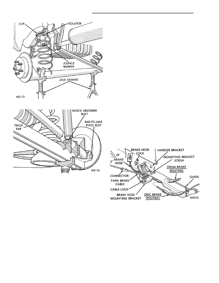
(6) Attach brake hose and parking brake cable to

caliper and suspension arm (Fig. 7). Install brake
hose mounting bracket to caliper support.

(7) Route park brake cable through hanger bracket

and lock housing end into bracket. Install cable end
into (intermediate) connector (Fig. 7).

(8) Install brake hose and fitting into bracket and

install lock. Attach brake tube assembly to hose fit-
ting and tighten to 16 N

Im (140 in. lbs.) torque (Fig.

7).

(9) Install wheel and tire assemblies and tighten

wheel stud nuts to 129 N

Im (95 ft. lbs.) torque. Re-

move jacks and lower vehicle.

(10) With suspension supporting vehicle, torque

lower shock absorber bolts to 61 N

Im (45 ft. lbs.).

Then torque track bar bolt to 95 N

Im (70 ft. lbs.).

(11) Bleed brake system. See BRAKES, Group 5.

Fig. 5 Install Springs and Isolators

Fig. 6 Install Shock Absorber and Track Bar

Fasteners (Bolts)

Fig. 7 Reconnect Brake Tube and Park Brake Cable

2 - 58

SUSPENSION AND DRIVESHAFTS

Ä

AUTOMATIC AIR LOAD LEVELING SYSTEM

INDEX

page

page

Compressor Performance Test

. . . . . . . . . . . . . . 61

Compressor Relay

. . . . . . . . . . . . . . . . . . . . . . . . 72

Control Module

. . . . . . . . . . . . . . . . . . . . . . . . . . 72

General Information

. . . . . . . . . . . . . . . . . . . . . . . 59

Major Components

. . . . . . . . . . . . . . . . . . . . . . . 59

Rear Leveling Diagnostic Procedures

. . . . . . . . . 65

Right Shock Absorber (With Height Sensor)

. . . . 72

Service Procedures

. . . . . . . . . . . . . . . . . . . . . . . 62

System Operation

. . . . . . . . . . . . . . . . . . . . . . . . 61

GENERAL INFORMATION

The automatic air load leveling system includes

the following (Fig. 1).:
• Compressor Assembly

• Control Module Wiring Harness

• Air Lines

• Compressor Relay

• Air Shock Absorbers

• Air Dryer

This system is used to supplement standard sus-

pension systems on vehicles so equipped.

MAJOR COMPONENTS

COMPRESSOR ASSEMBLY

The compressor assembly is driven by an electric

motor and supplies air pressure between 1172 to
1516 kPa (170 to 220 psi) (Fig. 2). A solenoid oper-
ated exhaust valve, located in the compressor head
assembly, releases air when energized.

CONTROL MODULE

The Control Module (CM) is a device that controls

the ground circuits for the compressor relay and the
exhaust valve solenoid. A microprocessor within the
module limits the compressor pump operation time to
140 to 160 seconds. To prevent damage to the com-
pressor motor.

Fig. 1 Automatic Air Load Leveling System

Ä

SUSPENSION AND DRIVESHAFTS

2 - 59

In addition, there is an air regeneration cycle that

is controlled by the Control Module (CM). If the
height sensor signal is in the neutral or high posi-
tion. When the ignition switch is turned to the ON
position, after a 22 to 28 second delay, the compres-
sor will run from 2 to 6 seconds.

To prevent excessive cycling between the compres-

sor and the exhaust solenoid circuits during normal
ride conditions. A 12 to 18 second delay is incorpo-
rated in the microprocessor.

HEIGHT SENSOR

A magnetic switch type sensor, located in the right

air shock absorber, monitors rear vehicle height. The
sensor sends signals to the (CM) relating to vehicle
rear suspension status (low, trim, high).

AIR LINES AND FITTINGS

To release an air supply line from a rear shock ab-

sorber assembly. Push in (toward shock absorber) on
the plastic ring of the shock absorber air line fitting.
Then while holding in the plastic ring on shock ab-
sorber fitting pull the air supply line strait out of fit-
ting (Fig. 3).

The fitting has a unique push-in feature. A brass

type collet locks the air line in place. One rubber
O-ring seals the air line to prevent air leakage. To
attach air line, push into fitting (Fig. 4).

COMPRESSOR RELAY

The relay is mounted to a bracket on the Control

Module (CM). When the relay is energized, it allows
the compressor to operate. This unit is controlled by
the CM.

AIR ADJUSTABLE SHOCK ABSORBERS

Air shock absorbers are essentially hydraulic shock

absorbers with a neoprene bladder sealing upper and
lower sections together. This creates an air cylinder
inside of the shock absorber.

AIR DRYER

The air dryer is attached to the compressor. This

component serves two purposes; it absorbs moisture
from the atmosphere before it enters the system. And
with the internal valves maintains a residual system
pressure of 69 to 152 kPa (10 to 22 psi).

AIR CHECK, RESIDUAL (FIG. 5).

The air dryer has a valves arrangement that main-

tains 69 to 152 kPa (10 to 22 psi) in the air shocks.
This is to improve the ride characteristics of the ve-
hicle under light load conditions. To test this func-
tion, perform the following procedure:

(1) Remove the air line from the dryer and right

shock absorber. Attach a piece of bulk nylon tubing
to one side of a Pressure Gauge (0-300 psi), and to
the right shock absorber (Fig. 5).

(2) Attach another piece of nylon tubing from the

dryer (compressor) to other side of the pressure
gauge.

Fig. 2 Compressor Assembly

Fig. 3 Release Air Line from Fitting

Fig. 4 Push Air Line into Fitting

2 - 60

SUSPENSION AND DRIVESHAFTS

Ä

A compression ball sleeve nut and sleeve for 3/16

inch tubing with ball sleeve connector and an inter-
nal pipe T-fitting. Can be used to attach the tubing
to the pressure gauge.

(3) Cycle ignition from OFF to ON.
(4) Apply a load to the rear of the vehicle (two as-

sistants or approximately 300-325 lbs.) to run com-
pressor and raise the vehicle.

(5) Remove the load applied in Step 4. Allow the

system to exhaust and lower the vehicle.

(6) When no more air can be exhausted, the gauge

should indicate 69 to 152 kPa (10 to 22 psi).

(7) Remove the pressure gauge and nylon tubing.

Attach the air line between the dryer and shock ab-
sorber. Repeat Steps 3, 4, and 5 to ensure system air
pressure is in the shocks.

LEAK CHECKS

(1) Repeat Residual Air Check Steps 1, 2, 3, and 4.

Allow the system to fill until gauge reads 483 to 621
kPa (70 to 90 psi).

If compressor is permitted to run until it reaches

its maximum output pressure, the vent solenoid
valve will function as a relief valve. The resulting
leak down, when compressor shuts off, will indicate a
false air leak.

(2) With load still applied, disconnect wire harness

connector from the control module, then remove ap-
plied load. Vehicle should rise. Cycle ignition switch
to OFF.

(3) Observe if pressure leaks down or holds steady

(wait approximately 15 minutes).

(A) If system will not inflate beyond 345 kPa (50

psi). A severe leak may be indicated. Check for a
pinched

pressure

line

between

compressor

and

shocks.

(B) The standard soap solution check procedure is

acceptable.

(C) If pressure holds steady, perform the diagnosis

procedures.

SYSTEM OPERATION

RAISING VEHICLE HEIGHT

When weight is added to the rear suspension. The

body of the vehicle is lowered, moving the height
sensor down.

This action will activate the internal time delay

circuit. After a time delay of 12 to 18 seconds. The
control module (CM) activates the ground circuit to
the compressor relay.

With the relay energized, the compressor motor

runs and air is sent through the system. As the
shock absorbers inflate, the body moves upward to a
corrected position. When the body reaches the correct
height, the control module (CM) stops the compressor
operation.

LOWERING VEHICLE HEIGHT

When the weight is removed from the vehicle. The

body moves upward, which allows the height sensor
to move upward and activate the internal time delay
circuit.

After a time delay of 12 to 18 seconds. The (CM)

activates the exhaust solenoid circuit. Air is ex-
hausted from the shock absorbers through the air
dryer and exhaust solenoid to the atmosphere.

As the body lowers, the height sensor is lowered to-

ward its original position. When the body reaches the
original vehicle height, the (CM) opens the exhaust
solenoid valve circuit.

COMPRESSOR PERFORMANCE TEST

This test can be performed on the vehicle. It is

used to evaluate compressor current draw, pressure
output, and leak down.

(1) Disconnect the compressor motor wiring har-

ness connector.

(2) Disconnect air line between dryer and right

shock absorber.

(3) Connect an air pressure gauge into the system

(Fig. 5).

(4) Connect an ammeter in series between the red

wire terminal on compressor connector and a 12 volt
power source. Also, connect a ground wire from the
black wire terminal on the compressor connector to a
good ground on the frame (Fig. 6).

(5) If the current draw to the compressor motor ex-

ceeds 21 amperes, replace the compressor assembly.

(6) When the air pressure stabilizes at 827 kPa

(120 psi), disconnect the (+) wire lead from the con-
nector. Replace the compressor assembly if any of the
following conditions exists:

Fig. 5 Pressure Gauge Installed in System

Ä

SUSPENSION AND DRIVESHAFTS

2 - 61


Content   ..  88  89  90  91   ..