Chrysler Le Baron, Dodge Dynasty, Plymouth Acclaim. Manual - part 85


  Index      Dodge     Chrysler Le Baron, Dodge Dynasty, Plymouth Acclaim - service repair manual 1993 year


Search            


Content   ..  83  84  85  86   ..


Chrysler Le Baron, Dodge Dynasty, Plymouth Acclaim. Manual - part 85


ing, do not remove the heavy spacer ring from the
shaft, G.K.N. only (Fig. 4).

(7) With joint separated from the interconnecting

shaft proceed as follows:
• If outer C/V joint was operating satisfactorily and
grease does not appear to be contaminated, just re-
place boot. Bypass the following disassembly proce-
dure for the C/V joint assembly, See Boots Install.
• If outer joint is noisy or badly worn. Bypass the
following disassembly and replace entire unit. It is
also recommended that the boot be replaced. The
Boot Package includes the boot, clamps, retaining
ring (circlip), and lubricant. See boots install.

(8) Hold joint vertically in vise by clamping on

splined shaft, using soft jaws to prevent damage.

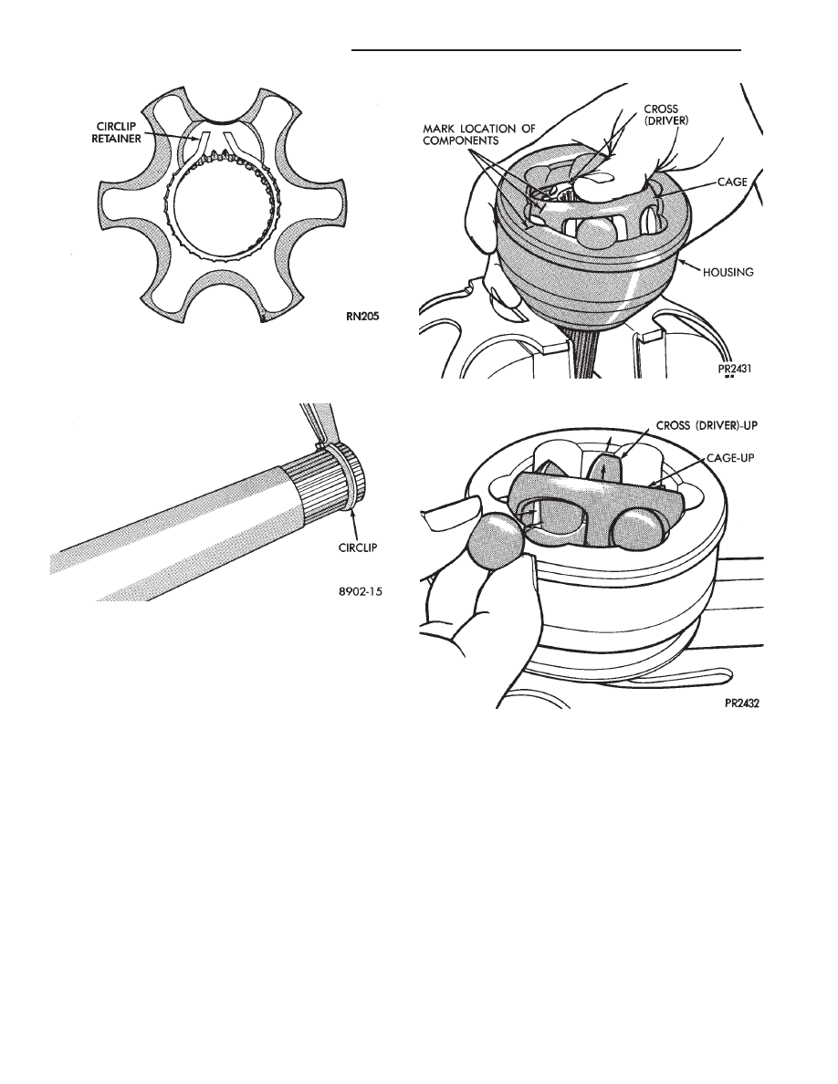
(9) Wipe off surplus grease and mark relative po-

sition of inner cross, cage and housing with a dab of
paint (Fig. 5).

(10) Press down on one side of inner race to tilt

cage and remove ball from opposite side (Figs.5 and
6). If joint is tight, use a hammer and brass drift to
tap inner race. Do not hit the cage. Repeat this step
until all 6 balls are removed. A screwdriver may be
used to pry balls loose.

(11) Tilt the cage and inner race assembly verti-

cally and position two opposing cage windows in area
between the ball grooves. Remove the cage and inner
race assembly by pulling upward away from the
housing (Fig. 7).

(12) Turn inner cross (driver) 90° to cage and align

one of the race spherical lands with cage window.
Raise land into cage window and remove inner race
by swinging out (Fig. 8).

INSPECT

Check grease for contamination and all parts for

defects as follows:

(1) Wash all parts in suitable solvent and dry,

preferably with compressed air.

(2) Inspect housing ball races for excessive wear

and scouring.

Fig. 3 Circlip Retainer in Cross S.S.G.

Fig. 4 Remove Circlip

Fig. 5 Rotate Cage & Cross to Remove Balls

Fig. 6 Ball Released

2 - 38

SUSPENSION AND DRIVESHAFTS

Ä

(3) Check splined shaft and nut threads for dam-

age.

(4) Inspect all 6 balls for pitting, cracks, scouring

and wear. Dulling of surface is normal.

(5) Inspect cage for excessive wear on inside and

outside spherical surfaces, surface ripples on cage
window, cracks, and chipping.

(6) Inspect inner race (cross) for excessive wear or

scouring of ball races.

Any of the above defects will warrant replac-

ing the C/V assembly as a unit.

Polished areas in races (cross and housing) and on

cage spheres are normal and do not indicate need for
joint replacement. Unless they are suspected of caus-
ing noise and vibration.

ASSEMBLE

If outer joint was not disassembled nor the

wear sleeve damaged go to step 11.

(1) Position new wear sleeve on joint housing ma-

chined ledge (Fig. 1). Assemble Installer, Special Tool
C-4698 (Tool is provided with handle and dual purpose
drive head for installing wear sleeve onto C/V joint
housing and (head reversed) seal into knuckle). See
KNUCKLE BEARING SEAL.

(2) See (Fig. 1). Assemble tool and install wear

sleeve.

(3) Lightly oil all components before assembling

outer joint.

(4) Align parts according to paint markings.

Fig. 7 Removing Cage & Cross Assembly from

Housing

Fig. 8 Removing Cross from Cage

Fig. 1 Tool Set-Up for Wear Sleeve Installation

Ä

SUSPENSION AND DRIVESHAFTS

2 - 39

(5) Insert one of the inner race (cross) lands into

cage window (Fig. 2) and feed race into cage. Pivot
cross 90° to complete cage assembly (Fig. 3).

(6) Align opposing cage windows with housing

land and feed cage assembly into housing (Fig. 4).
Pivot cage 90° to complete installation.

When properly assembled the large counterbore in

the cross should be facing outward from the joint on
G.K.N. units (Figs.3 and 6). On the S.S.G. joint the
internal circlip in the cross will be facing outward
from the housing (Fig. 5).

(7) Apply lubricant to ball races from packet pro-

vided in boot kit and distribute equally between all
sides of ball grooves. One packet is sufficient to lu-
bricate the joint.

Fig. 4 Installing Cage & Cross into Housing

Fig. 5 Cage & Cross Assembled S.S.G.

Fig. 6 Cage & Cross Installed in Housing G.K.N.

Fig. 2 Installing Cross into Cage

Fig. 3 Cage & Cross Assembled G.K.N.

2 - 40

SUSPENSION AND DRIVESHAFTS

Ä

(8) Insert balls into raceway by tilting cage and in-

ner race assembly (Fig. 7).

(9) Fasten boot to shaft. See Boots Install.
(10) On G.K.N. units insert the new circlip, pro-

vided with kit in shaft groove. Do not over expand
or twist 
circlip during assembly (Fig. 8). The S.S.G.
unit has a reusable circlip retainer that is an inte-
gral part of driver assembly.

(11) Position outer joint on splined end with hub

nut on stub shaft. Engage splines, and tap sharply
with mallet (Fig. 9).

(12) Check that circlip is properly seated by at-

tempting to pull joint from the shaft.

(13) Locate large end of boot over joint housing

checking that boot is not twisted.

(14) Fasten boot to housing. See Boots Install.

INTERMEDIATE SHAFT ASSEMBLY RECONDITION

Reconditioning of intermediate shaft assembly (Fig.

1), for Equal Length Drive Shaft System vehicles is
the same for manual and automatic transaxles.

INTERMEDIATE SHAFT ASSEMBLY

REMOVE

(1) Remove right driveshaft. See Driveshaft As-

semblies Remove.

(2) Remove speedometer pinion from the extension

housing (Fig. 2).

(3) Remove the two bolts which mount the bearing

assembly bracket to the engine block (Fig. 1).

(4) Remove assembly from transaxle extension by

pulling outward on the yoke (Fig. 3).

UNIVERSAL JOINT AND ROLLER

Disassemble

(1) Mark relationship of shaft to shaft to ensure

proper alignment at assembly. Apply penetrating oil
to bushings and remove snap rings.

(2) Support yoke in vise and place a socket large

enough to receive bushing on top of yoke. A 1-1/8
inch socket is suitable (Fig. 4).

(3) Striking socket with hammer will cause yoke to

move down and bushing to move up out of yoke into
socket.

(4) After removing one bushing, turn parts in a

vise and remove other bushing in same manner.

Assemble

(1) Hold cross in position between yoke ears with

one hand and start one bushing assembly into yoke
with other hand (Fig. 5).

(2) Continue to hold cross in position, then ham-

mer bushing assembly into yoke and install snap
ring.

(3) Install opposite bushing and snap ring in the

same manner.

Fig. 7 Inserting Balls into Raceway

Fig. 8 Installing New Circlip

Fig. 9 Position Joint onto Shaft Splines

Ä

SUSPENSION AND DRIVESHAFTS

2 - 41


Content   ..  83  84  85  86   ..