Chrysler Le Baron, Dodge Dynasty, Plymouth Acclaim. Manual - part 43
sition, the PCM monitors the crankshaft position and
camshaft position sensor signals to determine engine
speed and ignition timing (coil dwell). If the PCM
does not receive the crankshaft position sensor and
camshaft position sensor signals when the ignition
switch is in the Run position, it de-energizes both re-
lays. When the relays are de-energized, battery volt-
age is not supplied to the fuel injector, ignition coil,
fuel pump and oxygen sensor heating element.
The ASD relay and fuel pump relay are located in
the power distribution center (Fig. 16).
IDLE AIR CONTROL MOTOR—PCM OUTPUT
The idle air control motor is mounted on the throt-
tle body (Fig. 14). The PCM operates the motor. The
PCM adjusts engine idle speed through the idle air
control motor to compensate for engine load or ambi-
ent conditions.
The throttle body has an air bypass passage that
provides air for the engine at idle (the throttle blade
is closed). The idle air control motor pintle protrudes
into the air bypass passage and regulates air flow
through it.
The PCM adjusts engine idle speed by moving the
idle air control motor pintle in and out of the bypass
passage. The adjustments are based on inputs the
PCM receives. The inputs are from the throttle posi-
tion sensor, camshaft position sensor, crankshaft po-
sition
sensor,
coolant
temperature
sensor,
and
various switch operations (brake and air condition-
ing). Deceleration die out is also prevented by in-
creasing airflow when the throttle is closed quickly
after a driving (speed) condition.
BAROMETRIC READ SOLENOID—PCM OUTPUT
The barometric pressure read solenoid is spliced
into the manifold absolute pressure (MAP) sensor
vacuum hose (Fig. 12). The barometric read solenoid
switches the pressure supply to the MAP sensor from
either barometric pressure (atmospheric) or manifold
vacuum. The PCM operates the solenoid.
Atmospheric pressure is periodically supplied to
the MAP sensor to measure barometric pressure.
This occurs at closed throttle, once per throttle clo-
sure but no more often than once every 3 minutes
and within a specified RPM band. Barometric infor-
mation is used primarily for boost control and start
fuel enrichment at various altitudes.
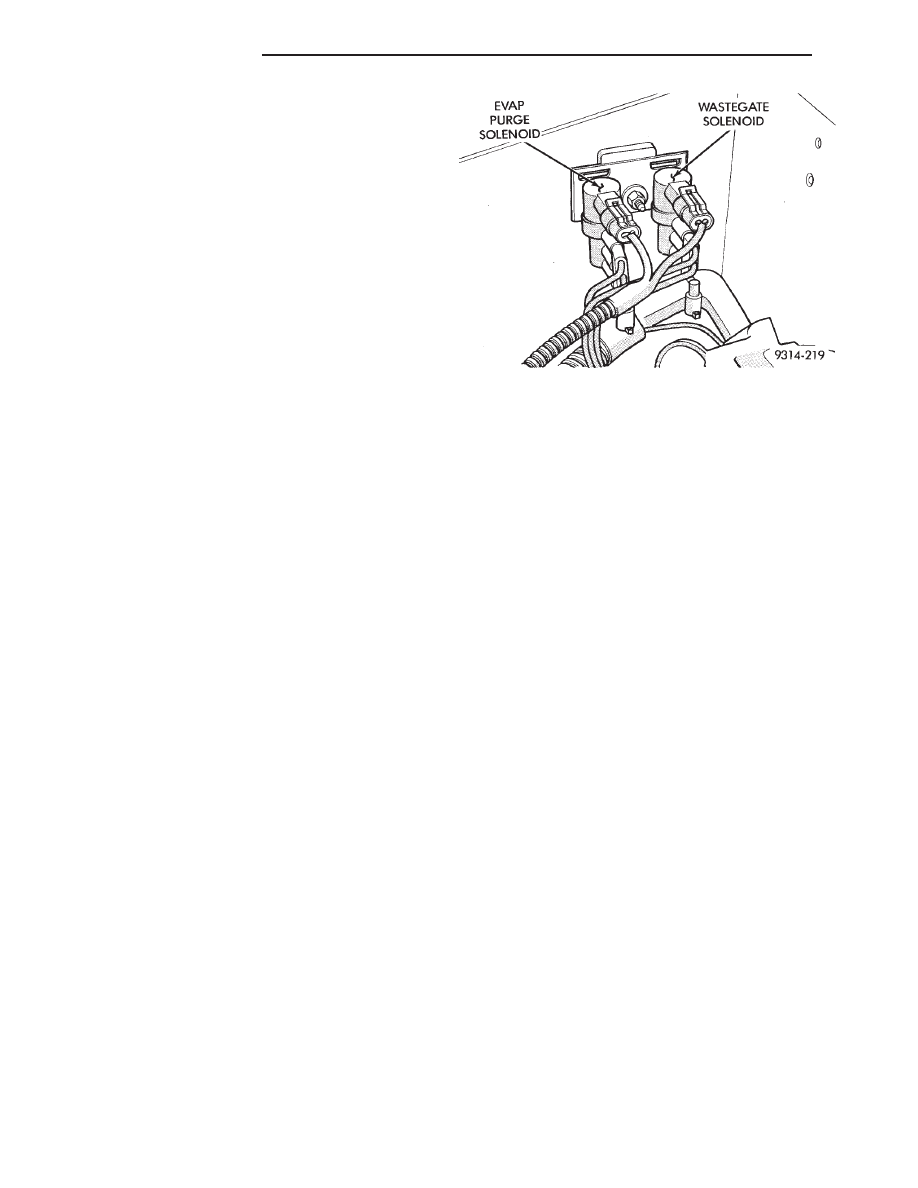
CANISTER PURGE SOLENOID—PCM OUTPUT
Vacuum for the Evaporative Canister is controlled
by the Canister Purge Solenoid (Fig. 17). The sole-
noid is controlled by the PCM.
The PCM operates the solenoid by switching the
ground circuit on and off. When grounded, the sole-
noid energizes and prevents vacuum from reaching
the evaporative canister. When not energized the so-
lenoid allows vacuum to flow to the canister.
During warm-up and for a specified time period after
hot starts the PCM grounds the purge solenoid.
Vacuum does not operate the evaporative canister
valve.
The PCM removes the ground to the solenoid when
the engine reaches a specified temperature and the
time delay interval has occurred. When the solenoid is
de-energized, vacuum flows to the canister purge
valve. Vapors are purged from the canister and flow to
the throttle body.
The purge solenoid will also be energized during
certain idle conditions, in order to update the fuel
delivery calibration.
MALFUNCTION INDICATOR LAMP (CHECK
ENGINE)—PCM OUTPUT
The malfunction indicator lamp (instrument panel
Check Engine lamp) comes on each time the ignition
key is turned ON and stays on for 3 seconds as a bulb
test. The malfunction indicator lamp warns the opera-
tor that the PCM has entered a Limp-in mode. During
Limp-in-Mode, the PCM attempts to keep the system
operational. The malfunction indicator lamp signals
the need for immediate service. In limp-in mode, the
PCM compensates for the failure of certain components
that send incorrect signals. The PCM substitutes for
the incorrect signals with inputs from other sensors.
Signals that can trigger the malfunction indi-
cator lamp (Check Engine Lamp).
• Engine Coolant Temperature Sensor
• Manifold Absolute Pressure Sensor
• Throttle Position Sensor
• Battery Voltage Input
• An Emissions Related System
• Charging system
The malfunction indicator lamp can also be used to
display diagnostic trouble codes. Cycle the ignition
switch on, off, on, off, on, within five seconds and any
Fig. 17 EVAP Canister Purge Solenoid and Waste-
gate Control Solenoid
14 - 90
FUEL SYSTEMS
Ä