Chrysler Le Baron, Dodge Dynasty, Plymouth Acclaim. Manual - part 22


  Index      Dodge     Chrysler Le Baron, Dodge Dynasty, Plymouth Acclaim - service repair manual 1993 year


Search            


Content   ..  20  21  22  23   ..


Chrysler Le Baron, Dodge Dynasty, Plymouth Acclaim. Manual - part 22


FUEL SYSTEM PRESSURE

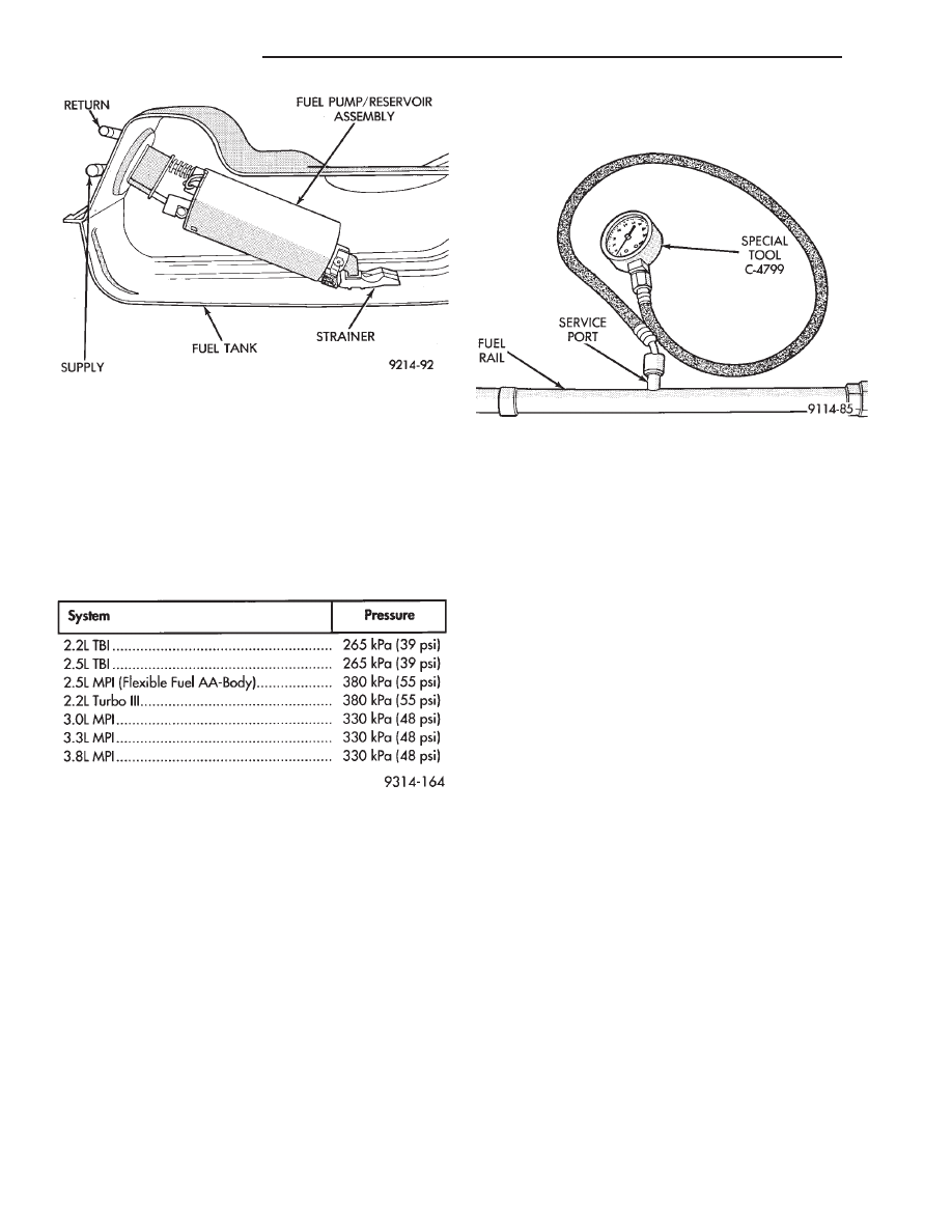
Fuel system pressure is regulated at the fuel rail

or throttle body by a fuel pressure regulator. Refer to
the Fuel System Pressure Chart for pressure specifi-
cations. The chart reflects system pressure when the
pump is energized with the engine not running and
without vacuum applied to the pressure regulator.

FUEL PUMP PRESSURE TEST—ALL EXCEPT
2.2L/2.5L TBI AND 3.0L MPI

WARNING: RELEASE FUEL SYSTEM PRESSURE
BEFORE SERVICING FUEL SYSTEM COMPONENTS.
WHEN

SERVICING

FLEXIBLE

FUEL

VEHICLES,

WEAR METHANOL RESISTANT GLOVES AND EYE
PROTECTION AND AVOID BREATHING FUMES. DO
NOT ALLOW METHANOL/GASOLINE MIXTURES TO
CONTACT SKIN. SERVICE VEHICLES IN WELL VEN-
TILATED AREAS AND AVOID IGNITION SOURCES.
NEVER SMOKE WHILE SERVICING THE VEHICLE.

The specifications in the Fuel Pressure chart re-

flect system pressure with the vacuum hose removed
from the pressure regulator.

(1) Remove the vacuum hose from the pressure

regulator before checking fuel pressure.

(2) Release fuel system pressure. Refer to the Fuel

System Pressure Release procedure in this section.

(3) Connect Fuel Pressure Gauge C-4799 to service

port on fuel rail (Fig. 6).

CAUTION: When using the ASD Fuel System Test,
the Auto Shutdown (ASD) Relay remains energized
for either 7 minutes, until the test is stopped, or un-
til the ignition switch is turned to the Off position.

(4) Place the ignition key in the ON position. Us-

ing the DRBII scan tool, access ASD Fuel System
Test. The ASD Fuel System Test will activate the
fuel pump and pressurize the system.

If the gauge reads the specification listed in the

Fuel System Pressure chart, further testing is not re-
quired. If pressure is not correct, record the pressure
and remove gauge. Use the DRBII scan tool ASD
Fuel System Test to pressurize the system. Ensure
fuel does not leak from the fuel rail service valve. In-
stall protective cover on fuel rail service valve.

If pressure is below specifications, proceed to Fuel

System Pressure Below Specifications . If pres-
sure is above specifications, proceed to Fuel System
Pressure Above Specifications
.

Fuel System Pressure Below Specifications
If the fuel pressure reading in step (4) was below

specifications, test the system according to the fol-
lowing procedure.

WARNING: RELEASE FUEL SYSTEM PRESSURE
BEFORE DISCONNECTING A FUEL SYSTEM HOSE
OR COMPONENT.

(a) Perform Fuel Pressure Release procedure.
(b) Install Fuel Pressure Gauge C-4799 and Fuel

Pressure Test Adapter 6539 in the fuel supply line
between the fuel tank and fuel filter at the rear of
vehicle (Fig. 7).

(c) Using the DRBII scan tool, with the ignition

key in the ON position, repeat the ASD Fuel Sys-
tem Test.

Fig. 5 Fuel Pump—Typical

FUEL SYSTEM PRESSURE

Fig. 6 Fuel Pressure Testing—Engines With Service

Ports

14 - 6

FUEL SYSTEMS

Ä

• If pressure is at least 5 psi higher than reading

recorded in step (4), replace fuel filter.

• If no change is observed, gently squeeze the re-

turn hose. If fuel pressure increases, replace pressure
regulator. If gauge reading does not change while
squeezing the return hose, the problem is either a
plugged inlet strainer or defective fuel pump.

Fuel System Pressure Above Specifications
If the fuel pressure reading in step (4) was above

specifications, test the system according to the fol-
lowing procedure.

WARNING: RELEASE FUEL SYSTEM PRESSURE
BEFORE DISCONNECTING A FUEL SYSTEM HOSE
OR COMPONENT.

(a) Perform Fuel Pressure Release procedure.
(b) Remove the fuel return line hose from the

fuel pump at fuel tank.

(c) Connect Fuel Pressure Test Adapter 6541 to

the return line (Fig. 8). Place the other end of
adapter 6541 into an approved gasoline container
or a container approved for methanol/gasoline mix-
tures (minimum 2 gallon size). All return fuel will
flow into container.

(d) Using the DRBII scan tool, with the ignition

key in the ON position, repeat the ASD Fuel Sys-
tem Test.
• If pressure is now correct, replace fuel pump as-

sembly.

• If pressure is still above specifications, remove

fuel return hose from chassis fuel tubes (at engine).
Attach Fuel Pressure Test Connect Adapter 6541 to
the fuel return hose and place other end of hose in
clean container (Fig. 9). Repeat test. If pressure is
now correct, check for restricted fuel return line. If
no change is observed, replace fuel pressure regula-
tor.

FUEL PUMP PRESSURE TEST—2.2L/2.5L TBI and
3.0L MPI ENGINES

WARNING: RELEASE FUEL SYSTEM PRESSURE
BEFORE DISCONNECTING A FUEL SYSTEM HOSE
OR COMPONENT.

The specifications in the Fuel Pressure chart re-

flect system pressure with the vacuum hose removed
from the pressure regulator. Remove the vacuum line
from the pressure regulator on 3.0L engines before
testing fuel system pressure. The pressure regulators
on 2.2L/2.5L TBI engines are not vacuum assisted.

(1) Perform fuel system pressure release.
(2) Remove fuel supply hose quick connector from

the chassis lines (at the engine).

(3) Connect Fuel Pressure Gauge C-4799 to Fuel

Pressure Test Adapter 6539 (Fig. 10). Install the
adapter between fuel supply hose and chassis fuel
line assembly.

Fig. 7 Fuel Pressure Test

Fig. 8 Fuel Pressure Return Test

Fig. 9 Fuel Return Connection

Ä

FUEL SYSTEMS

14 - 7

CAUTION: When using the ASD Fuel System Test,
the Auto Shutdown (ASD) Relay remains energized
for either 7 minutes, until the test is stopped, or un-
til the ignition switch is turned to the Off position.

(4) Place the ignition key in the ON position. Us-

ing the DRBII scan tool, access ASD Fuel System
Test. The ASD Fuel System Test will activate the
fuel pump and pressurize the system.

If the gauge reads the pressure shown in the Fuel

System Pressure chart, further testing is not re-
quired. If pressure is not correct, record the pressure
and remove gauge.

If pressure is below specifications, proceed to Fuel

System Pressure Below Specifications. If pressure
is above specifications, proceed to Fuel System
Pressure Above Specifications
.

Fuel System Pressure Below Specifications
If the fuel pressure reading in step (4) was below

specifications, test the system according to the fol-
lowing procedure.

WARNING: RELEASE FUEL SYSTEM PRESSURE
BEFORE DISCONNECTING A FUEL SYSTEM HOSE
OR COMPONENT.

(a) Perform Fuel Pressure Release procedure.
(b) Install Fuel Pressure Gauge C-4799 and Fuel

Pressure Adapter 6433 in the fuel supply line (Fig.
7) between the fuel tank and fuel filter.

(c) Using the DRBII scan tool, with the ignition

key in the ON position, repeat the ASD Fuel Sys-
tem Test.
• If pressure is at least 5 psi higher than reading

recorded in step (4), replace fuel filter.

• If no change is observed, gently the squeeze re-

turn hose. If fuel pressure increases, replace pressure
regulator. If the gauge reading does not change while
squeezing the return hose, the problem is either a
plugged inlet strainer or defective fuel pump.

Fuel System Pressure Above Specifications

If the fuel pressure reading in step (4) was above

specifications test the system according to the follow-
ing procedure.

WARNING: FUEL SYSTEM PRESSURE MUST BE
RELEASED BEFORE A FUEL SYSTEM HOSE OR
COMPONENT IS DISCONNECTED.

(a) Perform Fuel Pressure Release procedure.
(b) Install Fuel Pressure Gauge C-4799 and Fuel

Pressure Adapter 6433 in the fuel supply line be-
tween the fuel tank and fuel filter (Fig. 7).

(c) Remove the fuel return line hose from the

fuel pump at fuel tank. Connect Fuel Pressure Test
Adapter 6541 to the return line (Fig. 8). Place the
other end of adapter 6541 into an approved gaso-
line container or a container approved for gasoline/
methanol mixtures (minimum 2 gallon size). All
return fuel will flow into container.

(d) Using the DRBII scan tool, with the ignition

key in the ON position, repeat the ASD Fuel Sys-
tem Test.
• If pressure is now correct, replace fuel pump as-

sembly.

• If pressure is still above specifications, remove fuel

return hose from chassis fuel tubes (at engine). Attach
Fuel Pressure Test Connect Adapter 6541 to the fuel re-
turn hose and place other end of hose in clean approved
gasoline container or a container approved for metha-
nol/gasoline mixtures (Fig. 9). Repeat test. If pressure is
now correct, check for restricted fuel return line. If no
change is observed, replace fuel pressure regulator.

MECHANICAL MALFUNCTIONS

Mechanical malfunctions are more difficult to diag-

nose with this system. The powertrain control mod-
ule

(PCM)

compensates

for

some

mechanical

malfunctions. If engine performance problems are en-
countered, and no fault codes are displayed, the prob-
lem may be mechanical rather than electronic.

FUEL PUMP MODULE REMOVAL

WARNING: RELEASE FUEL SYSTEM PRESSURE
BEFORE SERVICING FUEL SYSTEM COMPONENTS.
WHEN

SERVICING

FLEXIBLE

FUEL

VEHICLES,

WEAR METHANOL RESISTANT GLOVES AND EYE
PROTECTION AND AVOID BREATHING FUMES. DO
NOT ALLOW METHANOL/GASOLINE MIXTURES TO
CONTACT SKIN. SERVICE VEHICLES IN WELL VEN-
TILATED AREAS AND AVOID IGNITION SOURCES.
NEVER SMOKE WHILE SERVICING THE VEHICLE.

Remove the fuel tank to service the fuel pump. Re-

fer to Fuel Tank Section for fuel tank removal.

(1) Using a hammer and a brass drift punch care-

fully tap lock ring counter clockwise to release pump
(Fig. 11).

Fig. 10 Fuel Pressure Gauge and Adapter

14 - 8

FUEL SYSTEMS

Ä

(2) Remove fuel pump and O-ring seal from tank.

Discard old seal.

FUEL PUMP MODULE INSTALLATION

WARNING: FUEL PUMP MODULES DESIGNED FOR
GASOLINE ONLY VEHICLES CANNOT BE USED ON
FLEXIBLE FUEL AA-BODY VEHICLES. WHEN SER-
VICING THE FUEL SYSTEM OF A FLEXIBLE FUEL
VEHICLE, ONLY USE ORIGINAL EQUIPMENT OR
EQUIVALENT REPLACEMENT COMPONENTS.

(1) Wipe seal area of tank clean and place a new

O-ring seal in position on pump.

(2) Position fuel pump in tank with locking ring.
(3) Using a hammer and brass drift, drive ring

around in clockwise direction to lock pump in place.

CAUTION: Over tightening the pump lock ring

may result in a leak.

(4) Install tank. Refer to the Fuel Tank Section in

this Group.

FUEL PUMP STRAINER SERVICE

WARNING: RELEASE FUEL SYSTEM PRESSURE
BEFORE SERVICING FUEL SYSTEM COMPONENTS.
WHEN

SERVICING

FLEXIBLE

FUEL

VEHICLES,

WEAR METHANOL RESISTANT GLOVES AND EYE
PROTECTION AND AVOID BREATHING FUMES. DO
NOT ALLOW METHANOL/GASOLINE MIXTURES TO
CONTACT SKIN. SERVICE VEHICLES IN WELL VEN-
TILATED AREAS AND AVOID IGNITION SOURCES.
NEVER SMOKE WHILE SERVICING THE VEHICLE.

REMOVAL

(1) Remove fuel pump module. Refer to Fuel Pump

Module in this section.

(2) Bend locking tabs on fuel pump reservoir as-

sembly to clear locking tangs on the fuel pump
strainer (Fig. 12).

(3) Pull strainer off.
(4) Remove strainer O-ring from the fuel pump

reservoir body.

(5) Remove any contaminants by washing the in-

side of the fuel tank.

INSTALLATION

WARNING: FUEL STRAINERS (AND O-RINGS) DE-
SIGNED FOR GASOLINE ONLY VEHICLES CANNOT
BE USED ON FLEXIBLE FUEL AA-BODY VEHICLES.
WHEN SERVICING THE FUEL SYSTEM OF A FLEX-
IBLE FUEL VEHICLE, ONLY USE ORIGINAL EQUIP-
MENT

OR

EQUIVALENT

REPLACEMENT

COMPONENTS.

(1) Lubricate the strainer O-ring with Mopar Sili-

cone Spray Lube.

(2) Insert strainer O-ring into outlet of strainer so

that it sits evenly on the step inside the outlet.

(3) Push strainer onto the inlet of the fuel pump

reservoir body. Make sure the locking tabs on the
reservoir body lock over the locking tangs on the
strainer.

(4) Install fuel pump module. Refer to Fuel Pump

Module in this section.

FUEL FILTER—ALL VEHICLES

WARNING: RELEASE FUEL SYSTEM PRESSURE
BEFORE SERVICING FUEL SYSTEM COMPONENTS.
WHEN

SERVICING

FLEXIBLE

FUEL

VEHICLES,

WEAR METHANOL RESISTANT GLOVES AND EYE
PROTECTION AND AVOID BREATHING FUMES. DO
NOT ALLOW METHANOL/GASOLINE MIXTURES TO
CONTACT SKIN. SERVICE VEHICLES IN WELL VEN-
TILATED AREAS AND AVOID IGNITION SOURCES.
NEVER SMOKE WHILE SERVICING THE VEHICLE.

Fig. 11 Fuel Pump Service

Fig. 12 Fuel Strainer Service

Ä

FUEL SYSTEMS

14 - 9


Content   ..  20  21  22  23   ..